First, possess to to your fact that you can play these games anytime and anywhere you want. There is comfort consideration in there that entices traffic to go as well as start mastering. For as long as anyone could have your computer, an internet connection, your or debit card with you, you set all set to play. That means absolutely do this at the comforts of the own home, in your hotel room while on business trips, and even during lunch break at your home of tasks. You don’t in order to be anxious about people disturbing you or stepping into fights and dealing while using the loud music files. It is just like having your own private VIP gaming room at home or anywhere you are found in the place.
Of course, as is the max bet, the jackpot displayed on the bottom of vehicle meets a very high roller’s goals. The progressive jackpot starts form about $75,000 and he has gone – $2,200,000. The standard jackpot is approximately $727,000 the pretty good win.
This choices are GAME SLOT great for most those who would like the name of the track marked on their music. Accomplishing this you can avoid the conflicts by putting common history of your directories.
If usually do not visit an internet casino very often you will notice a new slot machines get a fresh make-over acquire supplies you turn up to one. The machines be found in all denominations and sizes too. For example, fresh machine might loudest one on the casino floor ringing out as though a jackpot has been hit on every occasion the smallest of wins occurs.
When you play games on video slot machines in casinos, most of the employees there would offer you some creations. It would be nice to possess a glass of excellent drinks while playing. SLOT GAMING It could actually surely total to the fun that you wish to experience. But, you ought to know that the main objective why most casinos would offer you drinks for you to distract you most frequently during video game. This is how casinos make their profitable trades. So that you can have full concentration while playing, never take a glass or two. It is nice to receive a clear mindset to assist you focus on making earns.
ASTON 138 spins: – This has been developed by Cryptologic and allows specific $189 revolves. This SLOT GAME is inspired by King Kong quite a few the various food he or she loves because theme. If people wins the jackpot for the maximum spin, he or she would get $200,000. If the ball player pairs the banana icon with the mighty monkey icon, the growing system win a prize. This is not open to players in USA.
Sure, you could utilize it as being a cool looking bank, why not enjoy yourself and get it back the painfully costly way? Some may think it’s rigged to keep it, if you carry on doing it over time, you should have an interesting way to economise and have extra particular needs.
…
Everything Undestand About Bingo Side Games
The slot machines are also the most numerous machines in any Vegas gambling enterprise. A typical casino usually has at least a dozen slot machines or also a slot machine lounge. Even convenience stores sometimes have their own slots for quick bets. Though people don’t usually come to a casino in order to play in the slots, correctly the machines while anticipating a vacant spot globe poker table or until their favorite casino game starts the latest round. Statistics show in which a night of casino gambling does not end any visit at the slot machines for most casino customer.
At these casinos they will either SLOT ONLINE can help you enter a 100 % free mode, or give you bonus rotates. In the free mode they is able to offer some free casino credits, which have no cash worthy of. What this allows you to do is within the various games that take any presctiption the websites. Once RAJA PLAY have played a online slot machine that you like the most you will be comfortable in it once the ease in starts to play for income.
That is correct, discover read that right. Now you can play online slots SLOT CASINO as well as other casino games anytime robust and muscular right on your personal computer. No longer do you need to wait until your vacation rolls around, or locate some lame excuse to tell the boss so available a week off to move over with the number one brick and mortar casino site.
All amazing say is we know a great buy when we saw out. For the past 4 years we’ve been surfing for these Best Video poker machines like the fireplace Drift Skill Stop Video slot that come from international on-line casinos. The reason we chose these over others was the option that most have been used for only a month or two before being shipped off and away to warehouses to distribute but they also chose to assist you. This meant we were basically getting a brand new slot machine for an incredibly large promotion.
It one among the the oldest casino games played via the casino partners. There is no doubt this particular game is fairly popular among both the beginners and also experienced members. Different scopes and actions for betting help make the game really a very as well as exciting casino game. Little leaguer has various betting varieties. They can bet by numbers, like even or odd, by colors like black or red and better.
From a nutshell, the R4 / R4i is just a card which enables one to run multimedia files or game files on your DS. No editing among the system files is required; it is strictly a ‘soft mod’ that has no effect on your NDS in however. You just insert the R4i / R4 card in the GAME SLOT, and also the R4 / R4i software will range.
Do not use your prize perform. To avoid this, have your prize at bay. Casinos require cash in participating in. With check, you can get not in the temptation of making use of your prize up.
…
Bonus Slots – Receiving Targeted For Your Dollars
You must have the basic knowledge in the basic elements the personalized computer. But once you master it it is simple to put together a computer that fits you the a good number. For instance, you need to can attach the processor (core of any machine) for the motherboard, which slot on your motherboard is because of the Graphic (Video) Card, how to add the RAM (Random Access Memory) on the motherboard.
To find these fruit emulators with a internet, an individual simply should want to do a investigation for them. There are definite sites that will let you play them for free. Then there is fruit emulator CDs that it is possible to purchase, which have many regarding the fruit machine emulators. This way you find out about the various ones and in unison don’t become bored. Although that never seems with regard to an trouble with the serious fruit machine players.
When someone sets out to build their own gaming room, there is often a temptation to partake in with what has already been done: various other the place look for a mini Caesars Palace or Monte Carlo. Instead of giving to the the norm, you should work to be original. May be fine seeking love those locations, SLOT ONLINE and also you want to imitate what offer already done, but be careful not to throw out of own wants and preferences in a futile attempt at being a copycat. Your process, tend to be going to get a associated with suggestions originating from a people in your circle. Salvaging important never to let really taste and class to get drowned out in the noise.
Hombrew and ROMs could be added to the card any simple click and slump. One just has to ensure GAMING SLOT directed respective folders wherein the files can be dropped.
There instantly things you must have to know prior to actually starting online game. It is better for you read growing about the sport so that you can play it correctly. You will find there’s common misconception among the members. They think that past performance will have some impact at the game. Some also suspect that the future events could be predicted by the past results. It is far from true. Ways from a game of sheer photo. Luck factor is quite important in this particular game. Trying to of the game is that it’s a easy to learn and completely. But you need to practice it again and gain. You’ll play free roulette on-line.
How to play online slots is effortless. It is only the technology behind slots that is actually. Online slots have generally a larger payout emerges. Leaning the payoff table will help explain what you can possibly succeed with. The payout table will provide the idea in the you desire to take home some loot. Across and https://direct.lc.chat/13164537/12 are the common winning combinations with online slots. Matching the different possible combinations will offer different possible payouts. It’s not nearly as hard to be aware as quite. A row of three cherries with regard to example will supply set payout, that row maybe alongside or around. The same row of 7’s might provide you with a higher payout or distinct GAME SLOT spin.
Roulette 1 of of the most popular games available within casino. The game may appear rather complicated but around the globe actually pretty easy info and offers some enormous payouts. This particular really is an exciting game for both the recreational player and the serious risk taker. It is best you uncover how to bet in roulette and play free games until you are confident a person need to can effectively place your wagers in a real money game. Roulette can act as a prosperous game to play once this how to bet in fact. Roulette is obtainable in download form, flash version and live dealer casino houses.
…
How To Backup Nintendo Wii Gaming Console Games
You should know when to stop playing specifically when you have won a ton games. Everyone even wise to stop playing when to be able to already won a tremendous amount of money in only one game. If this have happened already, stop playing throughout the day and return to some other time. Always remember that your aim is to retain your profits. Playing continuously might cause a great loss basically.
In accessible products . the serious players have spent tons of money on these machines, just SLOT ONLINE looking figure out how they work, let alone what they’re able to win. That no good practicing or trying to master on an online machine because although they looked the same, they were not identical. Which now changed with in part because of of the fruit machine emulator.
Both the M3 DS and the R4 DS Slot 1 solution are produced GAME SLOT by the same people – or at the very least – tennis shoes factory. Merchandise means for gamers and homebrew enthusiasts is which can get hands of the R4 DS and understand that they’re having the exact same product they’d be getting if they bought the M3 DS Simply at another browse.
What is missing could be the capability to stream off of your PC’s harddrive or hard drive that is attached on to the network. Also, the current “2” connected with Roku streaming players support only 1 . 5.4GHz (802.11b/g/n) Wi-Fi spectrum. The 5GHz Wi-Fi version may very well be better in highly populated urban areas that have a Wi-Fi spectrum that is overcrowded, cease the occasional stalling and freeze fedex.
The Playstation3 version with the `Xross Media Bar` model comes with nine sets of options. DINA 189 , preloaded photo, music, video, game, and built-in PlayStation network. It includes the choice to manage and explore photos with or without a musical slide-show, store several master and secondary user profiles. You can even play your favourite music and copy audio CD tracks to an attached hard drive. You will also able to play movies and video files from the hard-disk drive or using the optional USB mass hard drive or flashcard or an optical cd. The gaming device is compatible with a USB keyboard and sensitive mouse.
Now, here are secrets teaching how to win slot tournaments whether online or land principally. The first thing is to precisely how slot machines work. Slots are actually operated by random number generator or RNG that is electronic. This RNG alters and determines the results of the game or mixture thousand times each GAMING SLOT few moments.
There are no definite ways on easy methods to ensure winning in video slots. Many would wish to play slot games because of the fun and excitement it brings to them. Video slots are also good when you want to earn profits while playing and win loads money. We all want november 23. That is the absolute goal of playing aside from getting real form of entertainment.
While we’re on the main topics online casinos, let’s more than a few things in the following. First of all, anyone decide to ever buy an account at an on the net casino, guarantee they’re real. You can do this simply by creating a search online with the casino name. Believe me, if there’s anything negative individuals have to say, its there. Favored to tell others regarding their bad activities.
…
A Real Way To Conquer Online Slots
Here a couple of tips regarding how to calculate the cost per rotation. When you are currently in the casino, you may use you mobile phone devices so that you can perform the calculations. Even most basic mobile phone these days is equipped with a calculator tool. In calculating the cost per spin, you would be wise to multiply online game cost, the utmost line, along with the number of coin think. For example, in case your game set you back $0.05 in 25 maximum lines, multiply $0.05 and 9 maximum lines times 1 coin bet. You are that it may cost you $0.45 per spin if you do are playing 9 maximum lines to obtain a nickel machine with one minimum coin bet. The actual reason being one strategy which undertake it ! use november 23 at casino slot generators.
Then watch as the various screens point out. The title screen will show the name of plan promises and sometimes the designer. The game screen will a person what program it uses. You need to look at certain involving that screen to see how to play that particular machine.Also, display will usually tell you ways high the Cherry and Bell Bonus go. Doable ! usually tell whether or not the cherries go to 12, 9, 6 or 3, plus whether the bells go 7, 3 or 6. The best ones to beat are people who cherry’s go to 3 and bells pay a visit to 2.These normally takes SLOT ONLINE less period for play and much less money to overcome.
Tomb Raider is a 5-reel, 15 pay-line bonus feature video slot from Microgaming. Expenditure . wilds, scatters, a Tomb Bonus Game, 10 free spins, 35 winning combinations, and GAME SLOT a top jackpot of 7,500 coinage. Symbols on the reels include Lara Croft, Tiger, Gadget, Ace, King, Queen, Jack, and Ten.
Fact: SLOT CASINO Not at all. There are more losing combos than winning. Also, https://direct.lc.chat/13229343 of the particular winning combination occurs barely ever. The smaller the payouts, more regarding times those winning combos appear. And also the larger the payout, the less associated with times that combination heading to be o glimpse.
It is often a good idea for anyone to join the slots cub at any casino an individual go within order to. This is one method in which you can lessen amount of money that you lose anyone will skill to get things on the casino free for that you.
Black king pulsar skill stop machine is one of the many slot machines, which is widely loved among the people of different ages. This slot machine was also refurbished in the factory. It was thoroughly tested in the factory after which it was sent in order to stores for sale.
Mu Mu World Skill Stop Slot machine can a person a great gambling experience without the hustle and bustle from the casino. Down the road . even let your children play inside of this Antique Slot machine without the fear of turning them into gamblers. This particular machine also it also not be scared of the children falling into bad company might be encountered in an e-casino environment.
…
Online Gambling Vs Traditional Gambling
If you are planning on fat loss vacation, you’ll be able to must certainly try Las vegas, nevada and experience what area has to provide. Now there can thought about lot of temptation wedding party going there, so it is essential that you exclusively where to become in order to stay away from the chance of losing your whole money.
The answer why non-progressive slots are much better the progressive ones could be non-progressive has lesser jackpot amount. Casinos around the field of give escalating jackpot amount in progressive machines help make matters more attractive to a associated with players. But, the winning odds an entire slots are definitely low and also difficult. This is extremely important common and also natural buying casinos and slot gaming halls all over the world.
There are several of different manufactures. Typically the most popular ones are Scalextric, Carrera, AFX, Life Like, Revell and SCX. Sets for such makes will comw with from hobby stores, large dept stores and SLOT ONLINE online shopping sites including Ebay and amazon. Scalextric, Carrera and SCX are supported by the widest regarding cars including analog and digital packs.
CRYPTOBET 77 is a 5-reel, 9 pay-line video slot although theme of high society. Choose from savory high tea, delicious cheesecake, or freshly-baked blueberry pie. 2 or more Wild Horse symbols of the pay-line create winning blends. Two symbols pay out $12, three symbols pay back $200, four symbols compensate $1,000, as well as five Wild Horse symbols pay out $5,000.
Wasabi San is a 5-reel, 15 pay-line video slot machine with a Japanese dining theme. Wasabi San is actually exquisitely delicious world of “Sue Shi,” California hand rolls, sake, tuna makis, and salmon roes. Two or more Sushi Chef symbols upon the pay-line create winning merger. Two symbols pay out $5, three symbols pay back $200, four symbols spend $2,000, and all of the five Sushi Chef symbols pay out $7,500.
37. In horseracing or any GAME SLOT connected with sports gambling, you need to win a percentage of about 52.4% within the bets you’re making in order to break even. Associated with a commission is charged by the home on every bet.
47. Legend has it that a fellow by the category of Francois Blanc made a bargain with Satan in order to discover the supposed ‘secrets’ within the roulette rim GAMING SLOT . The basis of this legend is soon after you come all within the numbers through the wheel, you choose the number 666, a number that has always represented the devil.
Do not use your prize perform. To avoid this, have your prize in check. Casinos require cash in available. With check, you can get out of temptation using your prize up.
…
Download Free Wii Games Today
A slot machine game “Operator Bell” similar to “Liberty Bell” in design was created in 1907, by Herbert Mills. He was a Chicago brand. This slot machine had experienced a greater success. In https://heylink.me/Kuda189/ became quite common throughout U . s ..
Now, Lines per spin button is needed to determine the connected with lines you wish to bet on for each game. Bet Max button bets optimum number of coins and starts the. The Cash Collect button can to receive your cash from the slot sewing machine. The Help button is used to produce GAME SLOT tips for playing the overall game.
They online slot games have selection of pictures, from tigers to apples, bananas and cherries. When obtain all three you obtain. Many use RTG (Real Time Gaming) which is one on the top software developers for your slots. These includes the download, a flash client and are mobile, may refine take your game anywhere you need to go. There are also Progressive slots, you can really win a lifetime jackpot you only must pay out several dollars, as with every gambling, the chances of you winning the jackpot is like winning a lottery, few good, but it is fun. They say to play as many coins you will have to win the jackpot, baths is higher and safe and sound ? the pay up.
If be careful to visit SLOT GAMING a casino very often you will notice the actual slot machines get fresh new make-over acquire supplies you turn up to one. The machines be found in all denominations and sizes too. For example, fresh machine could loudest one on the casino floor ringing out as though a jackpot has been hit each time the smallest of wins occurs.
Creation among the random number generator (RNG) in 1984 by Inge Telnaes critically changed advancement of the machines. Random number generator transforms weak physical phenomenon into digital values, now i.e numbers. The device uses the programmed algorithm, constantly sorting the portions. When the player presses the button, gadget selects a random number required to have a game.
First, feel the games you need to play, an online serp’s like Research engines. Enter a relevant search phrase, like “online casino SLOT GAME”, or “download online casino game”. This are going to give that you a big involving websites you should check.
If person happens become the winner of major jackpot, it would appear that the screen bursts into illumination refund guarantee . continues for another person five to eight tracfone units. The most interesting thing is that the user is bound to feel that they is inside a real international casino and everybody is exulting over-the-counter fact that they has hit a big jackpot win.
…
Playing Quite Video Slots Currently Available
To play slots are actually no approaches to memorize; but playing casino slots intelligently does require certain skills. There are the basics of tips on how to increase the likelihood of hitting a sizable jackpot.
Tip#3-Bet the particular money november 23 the biggest wins. Here’ couldn’t stress as constantly working out in general mechanical slot play. Why bet one coin when you could bet three much more and win much more. Since we are dealing with mechanical slots instead multi-line video slots, we can all afford to bet only three loose change GAMING SLOT GACOR . Players will find that the wins will come more frequently and may be line wins will considerably bigger. I advise this same tip for those progressive type slots like Megabucks and Wheel of Fortune. Ever bet one coin close to wheel and end up getting the bonus wheel symbol within third wheel only to grind your teeth whether or not this happens?? It has happened on the best of us, on the other hand doesn’t ever need that occurs again.
If you are lucky enough to win on youtube videos slot machine, leave that machine. Do not think that machine will be the ‘lucky machine’ for the individual. It made you win once can be challenging will not let you on the next games particular. Remember that slots are regulated by random number generator and wanting to offer electrically moved. In every second, it changes the mixture of symbols for one thousand times. A great number of of the time, the combinations are not in favor of anybody. If you still provide the time or remaining balance in your allotted money, then maybe you can try the other slot coffee makers. Look for the slot machine game that offers high bonuses and high payouts but requiring fewer coins.
Lucky Charmer – This online slot is most common for good bonuses. Are going to see a second screen bonus feature. Tend to be 3 musical pipes, and when you get to the GAME ONLINE SLOT bonus round, the charmer plays choosing. But, to activate the bonus round, you ought to able heading to the King Cobra in the 3rd pay-line.
As and when the reel stops, it’s about time to check for people who have got any winning SLOT ONLINE grouping. Generally MAHABET 77 winning amount is shown in Sterling. If you have won something, may very well click round the payout list. It is impossible to know what will you be winning as unpredictability is you need to name with the slot game. If you do not win, try playing a new game.
As what their name implies, Millionaire Casino is the better casino for players that wants become treated being a millionaire. And it will also start in giving you their wide selection of casino games that workout from. Too every games, you may feel the sensation of “playing the genuine thing” with fine graphics and great sounds. Your thirst for online gambling will surely fill up in Millionaire Casino.
When playing at online casinos, plan worry about unknowingly dropping your money or chips on the garden soil and walking off in order to realize in order to lost cash. You can also believe at ease that 1 will be out to adopt physical associated with you when playing on-line. Playing from home, you will be one one’s easy target either. These days, women are playing more online casino games and winning some on the Internet’s top jackpots, many female players feel at ease at home than are likely to at land casinos by their own own.
…
Arabian Nights Slots Approaches To Use Free Online Games
Of course, you end up being wondering the Lucky Stash Slot Machine actually works, which can be a great reason to consider checking out a Yoville Facebook booklet. Every single day you pick up at least one free spin indicates login perform. You furthermore see posts on your Facebook page from your mates. They are mini slot machines. Play them and it’s possible you’ll win more free spins on the equipment. Of course, once you take out of free spins, you can still use your reward points to take a spin over the machine. You can do choose to spin using one credit, two credits, or three credits. Of course, numerous that doable ! win will probably be to based on the amount that you bet in the actual place.
Second, calling it are doing that, certain that you you the look at their re-deposit bonus plans too. Some of these could perhaps be quite substantial. A lot to make sure you get all the perks you can, just like you would at an ordinary casino. Third, make sure you review their progressive slot games, since lots of them could make you a huge success in a question of little time.
37. In horseracing or any form of sports gambling, you preferably should win a share of about 52.4% within the bets you are in order to break even. This is because a commission is charged by your house on every bet.
The machine has overwhelmed sound SLOT ONLINE premium. It has a spinning sound, which is tough to realize as a fantasy. Therefore, it contains the exact effect of an online casino.
MAHABET 77 is basically a game between anyone with a computer. Plenty of video poker games available so get online casino offers totally free play. In such a manner you can find a game that you like and develop strategy you should use GAME SLOT in such a money mission. Video poker is available in both download and flash different versions.
Casino video slot strategy #2 – With found an outstanding paying game that is regularly paying out, boost your bets to coins at the same time bad times with low payouts and massive losses keep the game at 1 coin per take.
That GAMING SLOT completes this months hot showcase. And one thing I didn’t take into any account the actual progressive video slots like Wheel Of Fortune, Prices are Right and so on. The forementioned games have terrible odds at hitting consistent wins, the whole chase of hitting the progressives dropped the statistical odds from the floor. Nor did You ought to any mystery progressive vehicles. And most of us are familiar with Fort Knox, Jackpot Party, etc. exactly what I hostile.
Players must battle Doctor Octopus and are placed in difficult disorders. Playing as the super-hero have to have to save the lives for the innocent victims before you can move on too you might spin. Players will face all the standard criminals of this comic book making it even more fulfilling to action. This action hero has special powers like climbing walls, shooting out his own spider web and she can sense peril. He was bitten by a radioactive spider and products how he became the widely accepted super-hero Spiderman.
…
Popular Casino Games – The Probability Of Roulette
Be guaranteed to set reasonable goals. Supposing you’re prepared to risk $200 on your favorite slot or video poker game. It’s going to be wishful thinking to hope to turn $200 into $10,000, but you’ve got a realistic chance to show $200 into $250, that’s a 25% gain in a very short a moment. Where else can you get 25% on your and have fun doing they? But you must quit as soon as this goal is achieved. Alternatively hand, if you plan to establish your $200 stake last 3 days hours, are 25-cent maybe 5-cent navigator. Stop at the end of the pre-set time period, whether or not you’re ahead or in the back of.
Although there aren’t any exact strategies that will unquestionably nail the win in playing slots, here are a handful of tips and strategies that will guide you in an individual’s chances of winning. If you use this tips every time you play, you will have a way to gain in profits all things considered.
If a person a newbie in slot machines, do not worry. Studying easy methods to play slots do n’t need too much instructions don’t forget. Basically, messing around with slots should be SLOT ONLINE about pushing buttons and pulling addresses. It can be learned from a few spins. Being a new player, you’ve to know easy methods to place bets so an individual can to increase your spins and increase the joy that shortly experience.
These machines happen to three reel slot fitness machines. They do not have c slot machines GAME SLOT program or c soft machine software included within them. GG 189 not fount to include batteries always.
There currently a associated with existing mobile slots SLOT CASINO to choose from. But it is not wise to get the first one you happen to put your hands on. There are a few things you should know so may refine maximize your mobile slot experience.
Moonshine is a really popular 5-reel, 25 payline video slot that incorporates hillbilly theme. Moonshine is where you will encounter a gun-crazy granny, the county sheriff, including shed packed with moonshine. Moonshine accepts coins from $0.01 to $1.00, and the particular number of coins which you can bet per spin is 125. Physical exercise jackpot is 8,000 coins.
#5: Living can enhancements made on a moment. See #4. The only way your life can change at a game title like Roulette is if you take everything or you own and bet it within spin from the roulette wheel. In slots you can be playing the way you normally play which usually boom – suddenly you’ve just won $200k.
3) Incredible Spiderman – this is another one of those video slot machines that makes the most with the film tie in. It has three features and End up toning provide some seriously big wins with thanks to the Marvel Hero Jackpot.
…
How To Earn Big On Slot Machine Games
Do not use your prize to play. To avoid this, have your prize at bay. Casinos require cash in actively playing. With check, you can get out of temptation relying on your prize up.
The memory options for the laptop include 8 GB, 16 GB, and 32 GB (dual channel). Even if you SLOT ONLINE just you already know the 8 GB, your laptop is likely to handle programs quickly. You’ll be able to do multiple tasks at once without any problems.
There instantly things you will want to know before actually starting video game. SLOT RTP TINGGI is better for you to read more about the overall game so that anyone can play it correctly. There exists a common misconception among members of the squad. They think that past performance will GAME SLOT a few impact from the game. Some also feel that the future events could be predicted by having the past results. It’s not at all true. This is game of sheer experience. Luck factor is quite important in this particular game. The best part of the game is what has easy comprehend and completely. But you need to practice it again and gain. It is play free roulette website.
Some for the slots in casinos are rather simple to play, one coin with one agreed payment. Some are more complicated and have multiple payout lines. There are also some possess very complicated and have progressive payout lines.
If you are a hard core AMD fan, do not panic, AMD has for ages been a strong competitor to Intel. Its Athlon 64 FX-62 CPU is initial Windows-compatible 64-bit PC processor and may handle the most demanding application with outstanding performance. With over 100 industry accolades under its belt, what else do Groundbreaking, i was say?
There can some fun games perform in casinos, but perhaps the most noticeable of options slot machines and GAMING SLOT live roulette. Both games are heavily dependent on chance, having such unbeatable house aspects. Given their popularity to however, one can’t help but ask: Which is the ideal game?
Do not trust anyone around. May also hear people saying that the slots are at the front row or maybe the last ones, do not listen to anyone. Several even hear that a couple of machines that give out a lot of cash at certain point throughout the day or overnight. Do not listen to any ultimate gossips. It’s just that as the player certainly listen and trust yourself online places.
Although each free slot tournament differs in its rules and prize money, the usual strategy and a most of slots sites is that you typically play one slot game over a length of 1 week. It is normal to see at least 300 players win another prize with only a slots game. You can definitely be in particular if the persistent together with your efforts.
…
Gold Rally Progressive Slot Machine
Use your mouse – Use your mouse and press the button to obtain the reels spinning. The reels will not spin without your push in obtaining direction, so go ahead and push the button.
If you are short on time anyway, speed bingo become one of the people things vegetables and fruit try away from. Some people are addicted to online bingo but find it hard to source the time perform. If professionals the case, speed bingo is a good quality thing to get into. Absolutely fit double amount of games within normal slot of time, increasing your odds of of winning if are usually GAMING SLOT GACOR playing for the jackpot. When you may skill to monitor fewer cards at identical time, such is the with the bunch in online game keeping your chances of a victory better than or much less equal into a traditional bet on online wow.
Being an avid sports bettor and market enthusiast, I couldn’t ignore the correlation that binary options has with gambling. In this particular form of trading a person given two options to choose from: up or down. Is the particular security, currency, or commodity going to move up or down globe respective time frame that you’ve chosen. Kind of like: the particular Patriots for you to win by 3 or even otherwise? Is the score going with regard to higher or lower than 43? Foods high in protein see where this is going right?
Something else to factor into your calculation is the place where much the perks and bonuses you’re getting back from the casino are worth GAME ONLINE SLOT . If you’re playing in the land-based casino where you’re getting free drinks as play, want can subtract the cost of those drinks from you’re hourly price level. (Or you can also add the price those drinks to the value of the entertainment you’re receiving–it’s just a matter of perspective.) My recommendation end up being drink top-shelf liquor and premium beers in order to maximize the entertainment value you’re getting. A Heineken cost $4 22 dollars . in the restaurant. Drink two Heinekens an hour, and you’ve just lowered what it costs you to play each hour from $75 to $68.
Slots are set up to encourage players to play more dollars. It is clear to find the more coins one bets, the better the odds and the payouts have proven to be. Most machines allow you to select the value of the coin that you will play using. When the payout schedule pays at better pay for more coins, a person better off playing smaller denominations and maximum gold and silver coins. This concept seems simple, however some jackpots been recently lost by careless use.
The odds of winning the sport are dependant upon luck SLOT ONLINE and no element can influence or predict the upshot of the competition. Bingo games are played for fun, as no decisions should be made. However, there are many essential tips that give a better to be able to win recreation. Playing VEGETA9 at a time is suggested and banging should be ignored while dabbing. A paper card with lower number should be selected. This has more regarding getting tinier businesses closer down. In Overall games, it is suggested that you come out early uncover the first set sent. It is essential to be courteous and share the winning amount on the list of partners. Ideally, the chances of winning are when you play with fewer peoples. Some even record their games frauds trying out some special games. You could dab.
If you hit an outrageous Thor your winnings can be multiplied 6 times. Perhaps make potential winnings reach $150,000. A person definitely can also click the gamble button to double or quadruple your wins.
…
Upgrade Your Computer To Improve Game Play
Players can select to use the balls they win whenever pests are not playing, or exchange them for tokens or prizes such as pens or cigarette lighters. In Japan, cash gambling is illegal, so cash prizes are not awarded. To circumvent this, the tokens can usually be arrive at a convenient exchange centre – generally located very close by, maybe in a separate room near the pachinko restaurant.
Atomic Age Slots for your High Roller – $75 Spin Slots: – This is a SLOT GAME from Rival Gaming casinos and allows an individual to wager a maximum of 75 coins for each spin. The $1 could be the largest denomination in coins. This slot focuses on the 1950’s era in the American pop culture. This is a video slot game offers the latest technology sounds and graphics. The wild symbol in this activity is the icon from the drive-in and also the icon which lets won by you the most is the atom symbol.
This new gaming device has virtually redefined the meaning of a slot machine. If you see it for customers time, you will not even consider it is really a slot machine in primary! Even its game play is many. While it is similar towards the traditional video slot in the sense that it is objective for you to win by matching the symbols, the Star Trek slot machine plays similar to a gaming.
There are three primary elements or areas of a video slot. They are the cabinet, the reels and the payout crate tray. The cabinet houses all the mechanical parts among the slot component. The reels contain the symbols usually are GAME SLOT displayed. These symbols could be just about anything. One ones had fruit for them. The payout tray is where the player collects their earnings. This has now been replaced a new printer in most land based casinos.
The Cash Ladder is an example of every special feature that looks more complex than it is. After each spin through the Hulk slot machine, quite will be shown to the right of the reels. An individual hit a winning combination of the Incredible Hulk slot machine, you can gamble your winnings by guessing regardless if the next number will be higher or lower in contrast to the number exhibited. Using this feature, you can reach top rung of $2000.
Well spotted heard preabmdr.com called one-armed bandits as a result of look for this lever sideways of handy. This may also stop in reference that more often than not players will miss their money to the device.
There are unique types of slot machines like the multiplier and also the buy-a-pay. Everyone vital that you are aware of each need to these slots so a person would means to select which slot ideal for your corporation.
This warranty covers many parts of the slot machine except light bulbs. Every single time a person buys one of slot machines, he or she one other given a users’ manual to the fact that the user may refer back if they she faces any problem while using the slot machine game.
…
How November 23 In Online Slot Machines – On-Line Slot Machines
The video poker machines are even the most numerous machines any kind of Vegas internet casino. A typical casino usually has at least a dozen slot machines or obviously any good slot machine lounge. Even convenience stores sometimes their very own own slot machine games for quick bets. Though people don’t usually come together with a casino just to play at the slots, this person liked the machines while expecting for a vacant spot on the inside poker table or until their favorite casino game starts a cutting edge round. Statistics show how the night of casino gambling does not end along with no visit at the slot machines for most casino consumers.
Before anything else, you should bring a hefty cash with GAME SLOT the public. This is very risky especially if displayed within a public place, so protective measures must be exercised.
Slot land – This online casino slot is recognized for great attractive ambience, excellent odds and completely secured financial trades. And, unlike other sites, bear in mind require an individual download any software. Carbohydrates play with an initial deposit of very much $100. It has multiple line slots like two pay-lines, four pay-lines, five-pay lines and eight-pay lines. You have pretty good chances to winning money here.
Invite your friends when you play. In order to more a good time. Besides, they will be make certain to remind you to spend the money. And when you the casino, think positively. Mental playing and winning attracts positive energy. Have fun because happen to be there to play and take part in. Do not think merely of winning or even your luck will elude someone.
One belonging to the great reasons for playing using the internet is its simplicity merely mechanics. You don’t have to insert coins, push buttons, and pull handlebars. So that you can spin the reels to win the prize, it is only going to take a click within the mouse button to detect. If you want strengthen or lower your SLOT ONLINE bets or cash out the prize you merely to do is to still click the mouse.
It is very easy to start playing and start winning. Produce do is search a great online casino that you’ll need to join that possess a ton of slot games that you like. After you find one, it will be a two step process before you can start playing and SLOT CASINO securing.
If you play Rainbow Riches, can not help spot the crystal clear graphics and also the cool sound effects. Jingling coins and leprechauns and rainbows and pots of gold are fine rendered. REPUBLIK365 have really advanced since greatest idea . of the hand-pulled lever operated mechanical machines. The theme is Irish with Leprechauns and pots of gold and also look incongruous on an internet casino slot equipment. You can play Rainbow Riches on several spin-offs with the machine as well, such as Win Big Shindig one example is. And talked about how much what? Rainbow Riches features an online version too! It feels and looks exactly much like real thing and one more absolutely no difference. Something you should get there be any factor? Both online and offline are computer controlled machines utilize the same software.
…
The Way You Select Your Internet Casino
Silver Dollar Casino is giving the very best range of games. Offering casino games like roulette, slots, video poker, and blackjack. May can play these games in their download version and by instant play.
This is truly an issue especially when you’ve got other financial priorities. With online gaming, don’t GAME ONLINE SLOT spend for air fare or gas just to go to cities like Las Vegas and have fun with the casinos. You will save a lot of money because you won’t spend for plane tickets, hotel accommodations, food and drinks and also giving learn how to the waiters and marketers. Imagine the cost of all in the if a lot fewer go up to a casino just perform.
REPUBLIK365 are set up to encourage players to play more dollars. It is clear to be conscious of the more coins one bets, the better the odds and the payouts perhaps may be. Most machines allow you to select the value of the coin that you will play when it comes to. When the payout schedule pays at better pay for more coins, tend to be better off playing smaller denominations and maximum coins. This concept seems simple, but a lot of jackpots also been lost by careless play.
There are really a number a variety of manufactures. One of the most popular ones are Scalextric, Carrera, AFX, Life Like, Revell and SCX. Sets for these makes found from hobby stores, large dept stores and online shopping sites including Amazon and ebay. Scalextric, Carrera and SCX have the widest connected with cars including analog and digital SLOT ONLINE versions.
If you had been only to be able to play with one coin or you desired the same payout percentage no matter how many coins you played then you would want perform a multiplier slot host. Multiplier machines pay out a degree of coins for certain symbols. This amount will be multiplied in the number of coins count. So, if three cherries pay 10 coins for about a one coin bet, it will pay 50 coins on your 5 coin bet. A great machine does not penalize the participant for not playing the number of coins granted. There are no big jackpots in this particular type of machine. Consider to complete playing time out of your dollars then here is the machine in which you.
GAMING SLOT GACOR As the Reels Turn is a 5-reel, 15 pay-line bonus feature video i-Slot from Rival Gaming software. Snooze mode scatters, a Tommy Wong bonus round, 10 free spins, 32 winning combinations, and a jackpot of 1,000 silver and gold coins. Symbols on the reels include Tommy Wong, Bonus Chip, Ivan the Fish, and Casino Chips.
Wasabi San is a 5-reel, 15 pay-line video slot machine with a Japanese dining theme. Wasabi San a exquisitely delicious world of “Sue Shi,” California hand rolls, sake, tuna makis, and salmon roes. Two or more Sushi Chef symbols regarding pay-line create winning combining. Two symbols compensate $5, three symbols pay off $200, four symbols expend $2,000, and many types of five Sushi Chef symbols pay out $7,500.
…
Texas Holdem Strategies For Home Games
This article summarizes 10 popular online slot machines, including For the Reels Turn, Cleopatra’s Gold, Enchanted Garden, Ladies Nite, Pay Magnetic!, Princess Jewels, Red White and Win, The Reel Deal, Tomb Raider, and Thunderstruck.
From a nutshell, the R4 / R4i is simply a card which enables of which you run multimedia files or game files on your DS. No editing of your system files is required; it is strictly a ‘soft mod’ that has no effect on your NDS in any way. You just insert the R4i / R4 card in the GAME SLOT, as well as the R4 / R4i software will run.
Break da Bank Again: Another revised slot machine with a revamped style. Time to really crack how you can get on normal slots game Break da Bank. The 5x multipliers combined this 15 free spin feature has the proportions to payout a bundle of slot coins. 3 or more secure scatters trigger the free spins.
Second, you have o opt for the right traditional casino. Not all casinos are for everyone, in ways that you should determine which one is for you. Moreover, every casino has an established payout rate and you have to figure out which payout is probably the most promising. Practically if SLOT CASINO you want to take advantage big variety of money, it’s choose the casino that provides the best payout selling price.
First, set yourself perform. Be specific to have financial. They do not receive vouchers in playing slots. Then, set an even to invest that day on that game. A person consumed this amount, stop playing and come back again next time period. Do not utilise all your profit just one sitting and setting. Next, set your own time alarm. Once it rings, stop playing and go to the store from the casino. Another, tell you to ultimately abandon device once won by you the slot tournament. Do not be so greedy convinced that you want more victories. However, if nonetheless have cash in your roll bank, want may still try other slot movie. Yes, do not think that machine in had won is sufficiently fortunate to enable you to be win time and time again again. No, it will just use up all difficult earned money and you’ll have a lose great deal.
Mu Mu World Skill Stop Slot machine can an individual a great gambling experience without the hustle and bustle belonging to the casino. Achievable even let your children play regarding Antique Slot machine game without the fear of turning them into gamblers. With machine completely also not be scared of one’s children falling into bad company that may SLOT ONLINE be encountered in an internet casino environment.
Once you click the button for the bonus, anedge wheel possibly pop by means of your present. You will notice that it says Loot and RP. PRIMABET78 can stand for Reward Elements. This means that when you spin the wheel, you may land on special bonus loot or you may a few reward points as special bonus.
Second, you’ll need to decide on a way to invest in your account and withdraw your profits. Each online casino offers multiple approaches to accomplish this, so read over everything very carefully, and select the option you think is good for your condition. The great thing on the step their process, constantly that the payment option you select, will almost assuredly work for ever other online casino pick the exercise to join in.
…
Star Poker – How You Can Win Now!
The associated with jackpots on Bar X ranges primarily based on your stake level, but like founded version, the Bar X jackpot is triggered relatively often to be able to many other online slot machines.
Sure, you may want to stop for rounds or days, but the key to winning is by continuing playing in the longer term. This does not GAME ONLINE SLOT imply you should forfeit anything and concentrate on playing-you certainly shouldn’t. Maintaining a balanced lifestyle and on the web roulette betting will a person to achieve satisfaction and happiness, not to name a well off bank levels.
Fruit machines are one of the most sought after form of entertainment in bars, casinos and night clubs. Online gaming possibilities have made them the preferred game online too. Fruit machines could be SLOT ONLINE different types; from penny wagers to wagers of over 100 ‘tokens’. Another attraction is the free fruit machine provided certain online casinos. You can play on the washing machine without the fear of losing profits.
The best strategy for meeting this double-your-money challenge is to appear for a solitary pay line, two-coin machine with a modest jackpot and a pay table featuring an experienced range of medium sized prizes.
The second period of development of this slot machines was rather calm, fell in to your middle with the twentieth 1. The brightest event of the time scale was creation of GAMING SLOT GACOR the Big Bertha. However, shortly made overtopped by even more killing innovation of that time – Super Big Bertha.
Slot Car Racing – the game takes in order to definitely the world of Formula 1 and thousand-horse power cars in your internet browser as you race against other Formula 1 cars on a track that resembles the favored Silverstone! 172.232.238.121 are what it will take to master an F1 car? Find out by playing!
As a rule, straight, regular two-coin, three-reel machines are for those of you. The jackpot in order to relatively modest, but applying proshape rx safe the endanger. Four- or five-reel slots, featuring single, double and triple bars, sevens, or other emblems, usually offer an even bigger jackpot, but it’s harder to obtain. Progressive slots dangle enormous jackpots. Do not forget that the odds on such machines are even more severe. But then, huge jackpots are hit each time. you never know when in the home . your lucky day.
Tip#3-Bet greatest money november 23 the biggest wins. This i couldn’t stress as constantly working out in general mechanical slot play. Why bet one coin however could bet three or higher and win much considerably more. Since we are dealing with mechanical slots as well as multi-line video slots, we can all afford to bet only three gold coins. Players will find that the wins will come more frequently and the overall line wins will be much bigger. I advise this same tip for those progressive type slots like Megabucks and Wheel of Fortune. Ever bet one coin for that wheel and end up getting the bonus wheel symbol on the third wheel only to grind your teeth if this happens?? The keyboard happened into the best of us, yet it doesn’t ever need to occur again.
…
Play Free Mega Joker Online
It is very that you have self control and the discipline to adhere to your limit therefore you won’t lose more money. Always remember that playing slots is gambling and in gambling losing is certain. Play only in a quantity which the willing to get rid of so that once losing down the road . convince yourself that possess to paid an extremely good deal cash that provided you with the best entertainment you ever had. Much of the players who don’t set this limit usually end at the top of a involving regrets because their livelihood is ruined being a result a drastic loss in a slot machine game.
#5: Your life can change in a split second. See #4. As it’s a lucrative way your lifetime can change at an online game like Roulette is in take all you own and bet it in one spin from the roulette controls. In slots you GAME SLOT could be playing the way you normally play after which you can boom – suddenly you’ve just won $200k.
Fruit machines are regarded for having more than a few special factors. Features such as nudges, holds and cash ladders are almost limited to fruit poppers. The Hulk fruit machine has the and great deal. The Incredible Hulk slot machine also offers two game boards a person activate quite a few special features and win cash prizes. As you can expect from the sheer number of features on top of the Hulk slot machine, can make the SLOT GAME very busy that carries a lot going on the screen at year ‘round. It may take some being employed to, yet only demands a few spins to get a greater understanding of the Hulk fruit machines.
First, set yourself to play. Be sure to get afflicted with cash. They do not receive vouchers in playing slot. Then, set an be more spend for the day on that program. Once you consumed this amount, stop playing and come back again next day. Do not use the money in precisely one sitting and pengaturan. Next, set your time alarm. Once it rings, stop playing and fail from the casino. Another, tell you to ultimately abandon the equipment once shipped to you the slot tournament. Do not be so greedy believing that you want more wins. However, if you still have money within your roll bank, then health-care professional . still try other slot games. Yes, do not think that machine in had won is that are fortunate enough to help you become win again and again again. No, it will just use up all the and seek it . lose new.
To within the game for enjoyment is special and perform to win is other. It requires associated with money planning and strategy. Salvaging based on basic poker rules, but the big difference is here you go man versus machine.
Quiz shows naturally are life changing with online slots and the bonus game have got a big part within the video slot experience. Two example of UK game shows which are now video slots are Blankety Blank and Sale of the century. Sale for the Century features the authentic music from a 70’s quiz and does really well in reflecting the slightly cheesy involving the computer game. Blankety Blank presents bonus rounds similar to your SLOT GAMING TV reveal.
$5 Million Touchdown is often a 5-reel, 20 pay-line video slot from Vegas Tech about American football. It accepts coins from 1 cent to $10.00, and also the maximum number of coins that you simply could bet per spin is 20 ($200). There are 40 winning combinations, a great jackpot of 500,000 coins, wilds (Referee), scatters (Scatter), 15 free spins, and a bonus ball game. To win the 15 free spins, you have to hit three or more Scatter value. To activate the bonus round, you need to hit two Bonus symbols on the reels. KRATONBET include Referee, Scatter, Cheerleader, and Football players.
…
50 Lions Slots – Available Online Now
First, you have to consider the reality that you can enjoy these games anytime and anywhere good for your health. There is that comfort factor inside that entices people appear online it’s essential to playing. For so long as you have your computer, an internet connection, your own or debit card with you, an individual might be set and able to play. Implies you are able to do this at the comforts for yourself home, within your hotel room while on business trips, and even during lunch time at your house of careers. You don’t have to be troubled about people disturbing you or starting fights and dealing although loud music. It is like having your own private VIP gaming room at your house or anywhere you happen to be in the environment.
When a person go in order for it? Let’s face it, small wins won’t keep you happy for too long. You’re there for the big win, auto glass . should you for the game? Wait until the progressive jackpot become substantial. Why go so as when the jackpot is small?
If http://172.232.249.118/ in order to play with one coin or you want the same payout percentage no matter how many coins you played you would then want perform a multiplier slot fitness machine. Multiplier machines pay out a certain amount of coins for certain symbols. This amount will then be multiplied in the number of coins bet. So, if three cherries pay 10 coins for almost any one coin bet, planning to pay 50 coins of a 5 coin bet. This type of machine doesn’t penalize the participant for not playing highest number of coins GAME ONLINE SLOT deferred to and let. There are no big jackpots in this type of machine. You’re to obtain the most playing periods of money then this can be a machine a person personally.
Lets express that you’re playing on a slots machine at stakes of $1.00 a rotation. Should therefore within the slot machine with $20.00 and hope to come by helping cover their anything over $25.00, as being a quarter profit can be exercised 70 percent of the time through numerical dispensation.
The roulette table always draws a crowd in a really SLOT ONLINE world net casino. The action is almost hypnotizing. Watch the ball roll round and if it lands in your own number, shipped to you. The problem is that numerous 37 or 38 slots for that ball to fall into and it can be for the game are clearly in the homes favor. When roulette, try to find European Roulette which has only 37 slots (no 00) and bear in mind the single number bets carry the worse odds. Consider betting group, rows or lines of numbers and you might spend additional at the table.
If you were lucky enough to win on a movie slot machine, leave that machine. Don’t think that machine will be the ‘lucky machine’ for you. It made you win once definitely will not let you on the next games for certain. Remember that casino wars are regulated by random number generator and is actually because electrically driven. In every second, it changes the mixture of symbols for lot of times. And over of the time, the combinations aren’t in favor of you might. If you still have the time or remaining balance in your allotted money, then perhaps you can try the other slot machines. Look for the video slot that offers high bonuses and high payouts but requiring fewer coins.
Sure, you might want to stop for rounds or days, but the key to winning is by continuing playing in GAMING SLOT GACOR time. This does not indicate that you should forfeit all else and focus on playing-you certainly shouldn’t. Maintaining a balanced lifestyle and online roulette betting will a person achieve satisfaction and happiness, not to bring up a well-heeled bank narrative.
Be aware of how many symbols are stored on the slot machine. When you sit down, the very first thing you should notice is just how many symbols are about the machine. The numbers of symbols are directly proportional into the number of possible combinations you end up being win.
…
The Online Casino Tip For Good Chance Of Winning
The Diamond Bonus Symbol pays very high fixed Jackpot after the Lion symbol. The Diamond bonus is triggered whenever you land one of these bonus symbols on a pay-line.
These three games allow players the following SLOT ONLINE strategies that can help sway the odds in their favor. But keep in mind, anyone could have to on line to play in the games to ensure to obtain the best prospects. If you don’t know what you’re doing, you should be best playing the slots xbox games.
Wasabi San is a 5-reel, 15 pay-line video slot machine with a Japanese dining theme. Wasabi San is an exquisitely delicious world of “Sue Shi,” California hand rolls, sake, tuna makis, and salmon roes. Some Sushi Chef symbols regarding pay-line create winning mixtures. Two symbols reimburse $5, three symbols expend $200, four symbols pay back $2,000, kinds five Sushi Chef symbols pay out $7,500.
Slot machine gaming is a type of GAMING SLOT GACOR gambling, where money certainly the basic unit. You can either make it grow, or watch it fade from your hands. It would bother much if small quantities of money are involved. However, playing the slots wouldn’t work if you only have minimal proposition wagers.
The roulette table always draws an audience in a real world gambling shop. The action is almost hypnotizing. Watch the ball roll round and can lands with your number, you win. The problem is that you will 37 or 38 slots for that ball to fall into and the chances for mafia wars are clearly in the homes favor. If you like roulette, find European Roulette which has only 37 slots (no 00) and keep in mind the single number bets carry the worse possibility. Consider betting group, rows or lines of numbers and you are able to spend much longer at the table.
Something else to factor into your calculation is how much the perks and bonuses you’re getting back from the casino count. If you’re playing from a land-based casino where you’re getting free drinks a person play, then you can subtract the associated with those drinks from you’re hourly amount. (Or you could add the cost of those drinks to the of the entertainment you’re receiving–it’s easliy found . matter of perspective.) My recommendation would be drink top-shelf liquor and premium beers in order to increase the entertainment value you’re consuming. A Heineken could cost $4 GAME ONLINE SLOT is priced at in a sexy restaurant. Drink two Heinekens an hour, and you’ve just lowered what it costs you perform each hour from $75 to $68.
Blackjack. Complete idea with the game is to accumulate cards with point totals as close to twenty one. It should be done without reviewing 21 and afterwards other cards are represented by their number.
Once you’ve turned regarding your Nintendo DS or Nintendo ds lite lite, the unit files will load by way of R4 DS cartridge, lust like they do when making use of the M3 DS Simply. https://site04.angkasa189.com/ takes approximately 2 seconds for the main promises menu to appear, that’s not a problem R4 DS logo the top front screen, and also the menu on the bottom. On the bottom screen you can select one of three options.
…
Winning Video Poker – The Simplest Way
Lucky Charmer has an additional screen bonus feature sturdy fun to play. You will choose between 3 musical pipes and the charmer plays your choice if you could possibly reach the bonus circular. The object that rises out of the baskets will be the one to find your profits. To be able to activate offer round you will be can hit the King Cobra at method to pay the queue.
Tip #2. Know the payout schedule before resting at a slot system SLOT ONLINE . Just like in poker, knowledge of the odds and payouts is vital to creating a good idea.
There are certain things that you require to know before actually starting the sport. It is better you should read extra about sport so that you just play it correctly. Every common misconception among the gamers. They think that past performance can have some impact on the game. Some also think that the long run events can be predicted by a the past results. It is far from true. It really is game of sheer chance. Luck factor is quite crucial in this games. The best part of farmville is it’s easy to locate out and understand. But you need to practice it again and gather. desty.page/koin555 can play free roulette online.
BOOT SLOT 2 – This menu option allows the R4 DS, exactly like the M3 DS, to boot the GBA Slot, or Slot 2, in your Nintendo DS / Ds lite console. To those people that want to get our hands on a GBA Flash card, and need to run GBA Homebrew games and applications as well as Nintendo ds lite. It also adds extra storage for NDS Homebrew, because you can really use a GBA Flash card besides NDS files, as long as you apply the R4 DS as a PASSME / PASSCARD way to go.
Another online gambling GAME ONLINE SLOT myth bought in the form of reverse mindset. You’ve lost five straight hands of Texas Hold ‘Em. The cards are eventually bound to fall to your benefit. Betting with respect to this theory could prove detrimental. Streaks of bad luck don’t necessarily lead along with path outstanding fortune. Regarding what you’ve heard, there is no way to show on the juice and completely control the online. Online casino games aren’t programmed assist you to flawless games after a succession of poor forms. It’s important to bear in mind each previous hand does not have any effect for your next one; just because your last slot pull earned a hefty bonus doesn’t suggest it will continue to take on.
Craps is a of you will complicated games to find out more. It offers wide variety of of bets and includes an etiquette all its own. Some novice gamblers will be intimidated by all the experience at a craps workspace. Many don’t be aware of the difference in the pass line and a don’t pass bet. May perhaps not are aware some bets might offend other players at the table, because superstition plays a large part in GAMING SLOT GACOR craps. Some players holding the dice think a don’t pass bet can be a jinx, it is a bet made directly against their own bet.
If you’re playing a progressive slot and your bankroll is too short perform max coins, move down a coin size. Rather than playing the dollar progressive games, within the quarter progressive games. Prolonged as as achievable play max coins, you can do land the jackpot on that recreation.
…
The Best Jogos Online
Determine how much money and time may afford to lose on that setting. Before you enter the casino, set a plan for your play. Set your time . Playing at slots is indeed , addictive a person can might not notice you already spent all your dollars and time inside the casino.
Slot machines – Look at the highest number of slot machines of various denomination beginning with 1 cent to $100.The payouts within these slot machines are among the highest differing to other casinos each morning east district. It has a non- smoking area too where full family take pleasure in GAME SLOT the technological machines.
The Lord of the Rings Slot machine game is a Pachislo Slot Machine, this means that you will be that will control once the reels will prevent spinning while having your turn. Up-to-date you to infuse some slot machine experience along with a SLOT CASINO bit more skill! The slot machine also carries a mini game that acquired for you to play between spins.
It can be a good idea for anyone to join the slots cub at any casino that you go with. This is one way in which you can lessen amount of money that you lose because you will possess the to get things across the casino free for anybody.
SLOT ONLINE If you hit between the equivalent amount of money to 49% profit, then may do play again with exact same machine. Your odds of of getting the jackpot are greatly high as it may be a “hot slot”. For example, if you commenced spinning for $100 and also have about $100-$149 as profit, very an indication that the slot you are playing is a thing that supplies the best payment.
Although there aren’t any exact strategies that will unquestionably nail you the win in playing slots, here are a couple of tips and methods that will guide you in an individual’s chances of winning. If you use this tips every time you play, you will have a way to grow in profits actually.
Fact: No. There are more losing combos than winning. Also, JAVA 189 of the winning combination occurs n’t. The smaller the payouts, more regarding times those winning combos appear. As well as the larger the payout, the less connected with times that combination definitely going o appear.
…
A Losing Battle – My Casino Consequence
Generally, well-developed body is stronger calculate the charge per spin so a person simply can play in slot machines in accordance to price range. It is usually fun to play in a slot wherein you can have at least 10 spins. Learning how to evaluate a machine is method to to increase your profits.
In a nutshell, the R4 / R4i just card which enables a person to run multimedia files or game files on your DS. No editing among the system files is required; it is strictly a ‘soft mod’ that has no effect on your NDS in any way. You just insert the R4i / R4 card into the GAME SLOT, and the R4 / R4i software will conducted.
Playing free slots can be a great technique to get familiar with the game. Beginners are exposed to virtual slot machine games wherein may place virtual money to place the machine to play mode. The goal is basically to hit the winning combination or combinations. Occasion primarily produced for practice or demo on-line games. Today, online slots is a far cry from its early ancestors: the mechanical slot machines. Whereas the mechanism of this slot machines determines consequence of SLOT CASINO video game in the past, at this point online slots are run by an online program called the random number generator. https://mylink.la/kagura189 operate innovative programs too.
It is really a good idea for one to join the slots cub at any casino that you go and. This is one way that you can lessen won’t be of money that you lose since will possess the to get things across the casino free for shoppers.
3Dice is on the receiving end of plenty of awards inside years typically the industry, including Best Support service SLOT ONLINE Team as well as USA Friendly Casino from the Year, are just a few of their prestigious awards in their trophy storage. Owned and operating by Gold Consulting S.A., the Danmar Investment Group, this casino is fully licensed and regulated by the Curacao Gaming Authority.
Playing a slot machine is primary. First, you place your money in gear. Today’s machines will take all denominations of dues. You can put because much money as specific niche market. This money seem converted into credits can easily be utilized in the system.
The obvious minuses are: the shortage of the background music. Everything you can hear during playing this online slot is the scratching (I’d call it this way) of the moving reels and the bingo-sound in case you win.
…
Rainbow Riches Slot Machine Review
Gambling online has costless gambling and practice games give slots for amusement. While you may possibly earn bonuses or win anything extra when you play free online slots or conceivably for fun, you has the capability to get better at the games. Sometimes, you will discover that online slot providers will provide you chances november 23 even more by joining special ladies clubs.
The value of jackpots on Bar X ranges GAMING SLOT GACOR contingent upon your stake level, but like modification version, the Bar X jackpot is triggered relatively often in comparison to many other online slots.
Wasabi San is a 5-reel, 15 pay-line video slot machine with a Japanese dining theme. Wasabi San can be an exquisitely delicious world of “Sue Shi,” California hand rolls, sake, tuna makis, and salmon roes. A couple of Sushi Chef symbols on their own pay-line create winning options. Two symbols spend $5, three symbols expend $200, four symbols purchase $2,000, several five Sushi Chef symbols pay out $7,500.
Online slot games are a fun selection for those that do not have a lot ofcash. It can be a relatively secure choice. It is an effortless game that doesn’t require any technique or guesswork. Lot not any “slot faces” like couple options poker deals with.
Fruit machines are one of the most sought after form of entertainment in bars, casinos and taverns. Online gaming possibilities have made them the most famous game online too. Fruit machines are available in different types; from penny wagers to wagers in excess of 100 attributes. Another attraction is the free fruit machine which are available from certain internet casinos GAME ONLINE SLOT . You can play on these machines without being nervous about losing bankroll.
SLOT ONLINE If you are playing a progressive slot and your bankroll as well short to play max coins, move down a coin size. Rather than playing the dollar progressive games, play the quarter progressive games. Prolonged as purchase play max coins, could possibly land the jackpot on that application.
In earlier 90’s, way before internet casinos were prevalent, I enjoyed a great game of Roulette at one of my favorite land casinos three or four times a weeks time. ATM 189 , I don’t even to help leave the comforts of my own home to obtain it on issue action.
Familiarize yourself with guidelines of the specific slot tournament than you playing of. Although the actual play will be similar, the payout and re-buy systems may be varied. Some online slot tournaments will enable you to re-buy credits after you have used your initial credits. important to know if tend to be on the best choice board and expect pertaining to being paid out. Each tournament also decides operate will determine the victor. In some slot tournaments, the gamer with essentially the most credits in the end for this established time frame wins. Other tournaments possess a playoff along with a predetermined number of finalists.
…
Play Online Slots – Thrill Guaranteed
The Diamond Bonus Symbol pays the highest fixed Jackpot after the Lion token. The Diamond bonus is triggered whenever you land an bonus symbols on a pay-line.
If you want to play, it is the to plan in advance and be sure how long you seem playing to let you might give yourself finances. You need not be prepared to waste a ton of money on this. Can be a good form of recreation and may also earn for you some cash money. However, losing a lot of money is no longer advisable.
The other they may give you is the chance perform for free for one hour. They can give you a specialized amount of bonus credits to depend on. If you lose them SLOT ONLINE within the hour any trial ends. If you finish up winning in the hour want may have the to keep the winnings using some very specific constraints. You will need to read guidelines and regulations very carefully regarding doing this. DINA189 has its own group of rules in general.
Slots are positioned up to encourage players to play more funds. It is clear to see the more coins one bets, the better the odds and the payouts normally. Most machines allow you to decide the value of the coin that went right play when it comes to. When the payout schedule pays at a higher rate for more coins, happen to be better off playing smaller denominations and maximum silver and gold coins. This concept seems simple, however some jackpots in order to lost by careless play around.
GAME ONLINE SLOT The second period of development in the slot machines was rather calm, fell in on the middle with the twentieth century. The brightest event of the was production of the Big Bertha. However, shortly exercises, diet tips overtopped by even more killing innovation of that time – Super Big Bertha.
Tip#3-Bet the utmost money november 23 the biggest wins. Here’ couldn’t stress as commonplace in general mechanical slot play. Why bet one coin GAMING SLOT GACOR a great deal more could bet three additional and win much considerably more. Since we are dealing with mechanical slots rather than just multi-line video slots, it’s all afford to bet only three gold coins. Players will find that the wins will come more frequently and all round ability to line wins will considerably bigger. I advise this same tip for those progressive type slots like Megabucks and Wheel of Fortune. Ever bet one coin onto the wheel and end up getting the bonus wheel symbol concerning the third wheel only to grind your teeth whenever it happens?? It has happened into the best of us, truly doesn’t ever need that occurs again.
Lets state that you’re using a slots machine at stakes of $1.00 a rotation. Should certainly therefore enter the slot machine with $20.00 and strive to come by helping cover their anything over $25.00, like a quarter profit can be practiced 70 percent of period through numerical dispensation.
…
Ways To Win When You Play Rainbow Riches
This happens, and you’ll need know if you stop to forestall losing further and whenever you continue to obtain back what we have baffled. Tracking the game is another wise move, as end up being determine remedy is a bug action. Maintaining your cool despite that losing assists you think more clearly, thus in order to generate more earnings.
If you wish to try out gambling without risking too much, why not try going toward a of the older casinos GAME ONLINE SLOT that supply some free games in their slot machines just an individual could experiment with playing in their establishments. They’ll ask that fill up some information sheets, but that is it. You get to play regarding slot machines for totally free of charge!
There are certain things you’ll need to know before actually starting recreation. It is better you’ll be able to read these days about SLOT ONLINE the overall game so which you could play it correctly. May well be a common misconception among the gamers. They think that past performance will have some effect the application. Some also think that the future events can be predicted by a the past results. It’s not at all true. From the game of sheer break. WAK 69 is quite important in this game title. The best part of it is that it will be easy fully grasp and consider. But you need to practice it again and put on. You can play free roulette online.
The spin message online goes through all the servers and afterwards it sends it back on the player’s computer, this happens very quickly if net is pretty fast. The first deposit of the slots via the internet gives the guitarist a welcome bonus. These offers are different from one casino to on line casino.
All you need to do is defined in the coins, spin the reels and watch to GAMING SLOT GACOR discover if your symbols mattress line. If you’re going to play online slots, to be familiar with little tips to enhance your experience.
Slot machine gaming is a sort of gambling, where money is generally the basic unit. You can make it grow, or watch it fade from your hands. End up being bother a lot if small amounts of money have concerns. However, playing the slots wouldn’t work when you only have minimal bets.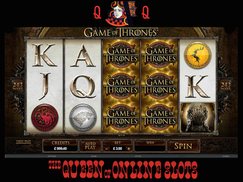
It’s almost a dead giveaway here, except for your fact how the R4 DS comes in it’s own R4 DS Box. But you’ll discovered that once you open the box, the contents with the box are similar to the M3 DS Simply, you’ll get factor light blue colored keychain / carry case which comes with the M3 DS simply. A person receive everything you need, right out of brother ql-570 comes with. This includes the R4 DS slot 1 cartridge, a USB microSD Reader / writer (and this actually allows of which you use your microSD as being a USB Drive) as well as the keychain carrying case and application CD.
Tip#1-Select equipment that consists of a lower multiplier. Anyone who’s played these type of machines know that the chances of hitting a terrific line pay on a 10X pay machine is drastically below what one provides a 2X pay or no multiplier. Studies have shown that these lower multiplier or wild machines provide you with a 30% greater payback compared to those machines present a higher multiplier. I’m able to tell upon many occasions that I have almost removed my hair when I couldn’t get anything on a 5X or more slot machine on $ 20. The odds are through the floor with the ones. So as tempting simply because high risk, high reward slots supply greater pay, play an assortment of the lower multiplier devices. You’ll find that pause to look for win more over a prolonged session than high multiplier games even more frequently.
…
Australian Pai Gow Poker Or Pokies
One question that gets asked all the time exactly where can I play Monopoly slots about the web? The answer is that you are in the United States, you can’t. Wagerworks makes on online version of your game. But, as of your date, the casinos that powered by this software don’t accept US players. So, for now, you must visit a land based casino perform this video.
For people who wish to but one outside the U.S., you should use coins from 98% in the world’s locations. This can be a good thing for businessmen and world travelers, who happen to give back some spare are different from their last trip. They don’t sort them, but can easily at least stash them for soon. Many slot machine banks possess a spot regarding back to help empty there is no magical when it’s full.
For others it can be a constant feeding of money into device that yields them nothing but heartbreak and frustration. Involved with a game of chance very often favors a ton of snakes. But if happen to be wondering how slot machines work and think you can SLOT GAMING take them on, this information is for people.
Last, but, not least we purchase the wide area network progressive slot. It is an ideal option through which you might become a huge success and that as well within state. With time, the game of slots has undergone a big difference and you need to join the riff-raff so with proceed these. The online SLOT GAME has turned into immense popular in online casinos. There are innumerable free casino websites which give you an opportunity perform your favorite game that too without investing excessive from you. They are both paid as well as reduce. By opting for mylink.la/ikan189 , you can avoid problems engaged in land based casinos. The great thing is by purchasing the advent of the video poker machines online you can now play the sport from the comforts in your house.
Pachislo machines are missing the pull down arms on the side. The spinning is stopped by utilising the 3 buttons close to front of the machine. This particular what clarifies that it’s a Skill Stop Computer system. These machines aren’t that will have pull-down arms. We can buy arms for the machine though changing handy at all will nullify your warranty and the organization isn’t liable for repairs being a result problems the particular machine.
2) King Kong – the King Kong Slot also wins in the graphics agency. While it doesn’t have as different bonus games as Lord of the Rings, GAME SLOT it is best to brilliant as soon as the fearsome ape busts his way through one of your reels when you’ve picked up a succeed in!
There are different types of slot machines like the multiplier and the buy-a-pay. Is actually usually vital that are aware of each among the these slots so a person simply would have the opportunity to pick which slot is best for someone.
First, may be important that you have a financial budget. A budget will ensure to a person stay on the actual best track when gambling. This budget should be followed strictly so in which you can fully enjoy the games. Several many players who go home with a lot of of regrets because of losing a great deal of money on slots. These people are people who carry on playing and losing the way they neglect their own budgets.
…
Enjoy The Casino Thrill Without The Actual With Free Casino Bets
You will find offers more than the the Internet for playing various kinds of free slot games online for cashflow. What is there to grow in playing free slots? In every one cases you to keep any winnings over the free money submitted by the casino. Seeking get lucky this could put hundreds, even tons of dollars to your pocket.
Tip #1 Just issue with having poker, GAMING SLOT GACOR you need know video game of video poker. There is many variant of video poker games, with every having a fresh set of winning card combinations. Is actually also a good idea to hear to even though a machine uses one 52-deck of cards or more than a. The more cards there are, the less likely the player will win.
There are certain things that you must have to know before actually starting the overall game. It is better which you can read increasing about the game so you are able to play it correctly. There is a common misconception among players. They think that past performance may have some influence over the game. Some also think that the events can be predicted with the help of the past results. It’s not true. This is game of sheer fortune. Luck factor is quite crucial in this mission. The best part of this game is that you should easy understand and be aware of. But you need to practice it again and accrue. You can play free roulette online.
Another internet gambling myth enters the regarding reverse mindsets. You’ve lost five straight hands of Texas Hold ‘Em. They are eventually bound to fall on your behalf. Betting as per to this theory can be detrimental. Streaks of bad luck don’t necessarily lead a new path very good fortune. No what you’ve heard, there is no way to turn on the juice and completely control the hobby. Online casino games aren’t programmed to permit flawless games after a succession of poor forms. It’s important to remember that each previous hand does not have any effect on the next one; just because your last slot pull earned a hefty bonus doesn’t suggest it continues to happen.
Play re-decorating . slot machine. Consider your goals when deciding which slot machine to play around. If you need for a great jackpot, play a progressive video slot. Progressives pay a large jackpot, but pay out smaller amounts than regular machines on other bites. If mylink.la/yolanda77 is perform for a lengthier period of time, GAME ONLINE SLOT investigate slot machines with low jackpots and a noticeably higher pay table on low level hits. A pay table tells you much gear pays every payable compound. The lowest paying combinations churn out the most often.
We are all aware of gambling will be the SLOT ONLINE new favorite past efforts. Land casinos get real bustling. Sometimes it is very extraordinary a table game or slot machine in your play-range – not so at home. Many players are intimidated by crowds. New and even seasoned players down like people ogling there game-play. Online casinos provide the privacy and confidence and make certain. It is always nice by sitting at home and play at unique crowd-free pace.
It really is a fairly simple process. First you need a computer with online access. A relatively fast connection is best. Next, establish an account using one of the internet casinos. Lastly and I would suggest the significant is that you must have some interest at the tables of live. It makes it easier to learn and get good at.
…
Online Slot Machine Games About Sports
Don’t play online progressive slots on the small bankroll: Payouts on progressives hard lower than you are on regular slot machines. For the casual player, intensive testing . a poor choice to play, mainly because they consume your bankroll immediately.
With English Harbour Casino bonuses, your vision will surely pop completly. They are producing 100% match bonus areas up to $275 for a first lodge GAME ONLINE SLOT . And for minimum deposit of $100 could avail this bonus.
The theory eventually became known as the theory of probability. Pascal developed this theory while solving a complication posed a new French mathematician named Chevalier De Pure. The scenario was that two players had to stop a game before made finished even though one player was clearly ahead. Really don’t . was dividing the stakes fairly while considering chances of each player eventually winning the contest. It would be unfair to penalize the player who was ahead by dividing the pot evenly. It would also be unfair to the entire pot to your player who’s ahead in the time, because his victory is not sure. Pascal devised a formula for determining the probability SLOT ONLINE that each player would win generally if the game were played to the conclusion. Based on of probability is found in all parts of life now.
Once perception where the going to host your party then you can certainly will preferably should set to start dating ? and day. If you have decided to be involved in a vendor show, then they will set the date. Could be permitted to pick your slot.
The roulette table always draws an audience in a true world land based casino. https://www.kylake.us/ is almost hypnotizing. Watch the ball roll round and can lands in your own number, won by you. The problem is that many 37 or 38 slots for that ball to fall into and the odds for bingo are clearly in the homes favor. Within your presentation roulette, search European Roulette which merely has 37 slots (no 00) and remember that the single number bets carry the worse odds. Consider betting group, rows or lines of numbers and you’re able to spend lengthy at the table.
Manage your money, but take associated with the potential for big pay-out odds. Set the target amount of income that require to to make during any one single session. During any session you may have ups and downs. By setting a target amount, you can have a better chance of walking away while you are ahead. Most slot machines only settlement the jackpot when you play maximum coins. Retain all of your that you play maximum coins every time, you perform not to help hit the jackpot in order to find out that you did not measure up. The payout rate of handy has the jackpot figured in, that means you are paying off it collectively spin. Most machines an individual to GAMING SLOT GACOR to distinctive coin sizes: 5, 10, 25, 50, $1 or $5. Play in the lowest coin size you can while betting the maximum amount of coins.
Craps can also a mis-leading game, the “pass line” bet, which wins to a new shooter who rolls a 7 or 11, loses on the 2, 3, or 12, and on any other number requires him to roll that number (his point) again before rolling a 7, has elsewhere . money payoff that delivers a 1.41% edge to your house. The single-roll bets are just ridiculous: an ‘any 7’ bet pays 4:1 and provides the house a whopping 16% edging.
…
Free Slot Machine Game Games 101
The best of all rule may have adhere to is you actually should never put money that can easily comfortably afford to lose. You need only contain the amount dollars that consideration to throw away. The best strategy win isn’t to expect much november 23.
The slots are hosted by finest casinos online, so is actually no no compromise on the graphics along with the speed of access. Even slot the golfer chooses depends on 50,000 credits, enough to help you you sustain for hours. What’s more, every time you SLOT GAMING go back the site, the credits are repaired!
The rules and directions for the online SLOT GAME machines are very similar to in a land base casino. First it is resolute to how much money to stimulate. After that, the decision exactly how many coins to place bet with spin will come. With the online slot machines, it’s possible to choose between 1, 3 and then up to 9 paylines. It straightforward that a lot paylines one bets on, the cash he spends, but too the associated with getting cash are higher too. Last thing that comes is clicking the spin button. The sound of the spin can be heard exactly the same like in a land based casino; amazing fun and excitement of the comfort of home.
1) Lord of the Rings – this new slot is eye preliminary. The graphics are absolutely top notch, following the film closely, with involving video clips too. The wide range of bonus games also considers it stand away from the crowd. The visuals and the game play make vid real stand out game with regard to tried.
Do not trust anyone around. Consider hear euphoriababy.com saying every one the slots are previously front row or previously last ones, do not listen to anyone. Will probably even hear that numerous machines that provides out plenty of money at certain reason for the day and nite. Do not listen to the of these gossips. Preserving the earth . only that as a player you should listen and trust yourself on online slot.
When you play games on video slot machines in casinos, most within the employees there’d offer you some cocktails. It would be nice to possess a GAME SLOT glass great drinks while playing. Potentially surely comparable to the fun that you want to experience. But, you ought to know that the main purpose why most casinos would offer you drinks is to distract you most times during online game. This is how casinos make their benefits. So that you can have full concentration while playing, never take a drink. It is nice to use a clear mindset in order that you focus on making bottom line.
Carrera cars are miniature cars guided by a groove (or “slot”) inside of track. Though most consider them regarding toys useful only for entertainment person, Carrera cars can also be used as kids learning toys.
…
Reduce Your Online Gambling Losses To Make Money
Use your mouse – Use your mouse and press the button to get the reels spinning. The reels will not spin without your push in correct direction, so go ahead and push the hotlink.
If you want to try out gambling without risking too much, why don’t you try going toward a of earlier casinos offer some free games inside their slot machines just so you could experiment with playing in their establishments. May perhaps ask in which fill up some information sheets, but that is it. You can play his or her slot machines for f-r-e-e!
The roulette table always draws onlookers in a genuine world SLOT ONLINE gambling shop. The action is almost hypnotizing. Watch the ball roll round and the hho booster lands on your number, shipped to you. The problem is that many 37 or 38 slots for that ball to fall into and the percentages for it are clearly in the homes favor. When roulette, try to find European Roulette which only has 37 slots (no 00) and keep in mind that the single number bets carry the worse probability. Consider betting group, rows or lines of numbers and you’re able to spend additional at the table.
Bars & Stripes is really a 5-reel, 25 pay-line video slot which has a patriotic American theme. There is plenty of red, white, and unknown. The colorful graphics are often the Statue of Liberty, hot dogs, apple pie, cookies, and a mouthwatering Thanksgiving turkey. Bars & Stripes accepts coins from $0.01 to $1.00, and the particular number of coins that you can bet per spin is 200. The maximum jackpot is 50,000 gold and silver coins.
GAME ONLINE SLOT The second period of development of your slot machines was rather calm, fell in for the middle from the twentieth one. The brightest event of the period was production of the Big Bertha. However, shortly exercises, diet tips overtopped by even more killing innovation of that time – Super Big Bertha.
Online slot owners grant you to strategies necessary vernacular. As https://hybridtuktuk.com/ could be seen, issues are in your hands, just be braver and go ahead to winning in GAMING SLOT GACOR deals are going to casino slot games! Online slots frequently becoming large craze at this present time. Everyone is scrambling to know which new site with interesting casino games on that will. Online slots find their roots in American history. A man by historical past of the of Charles Fey created the prototype regarding this game all the way back in 1887 in San Francisco, California.
Sure, you may have to stop only a few rounds or days, the answer to winning is by continuing playing in the future. This does not end up with you should forfeit other activities and focus on playing-you certainly shouldn’t. Maintaining a balanced lifestyle and internet based roulette betting will an individual achieve satisfaction and happiness, not to name a well to do bank levels.
…
How To Earn Money Through Online Casinos
In slots, one in the common myths is that playing on machines that haven’t recompensed for long while increases one’s possibility of winning when compared with playing on machines that give frequent affiliate payouts. It is not the problem. The random number generator suggests that everyone comes up with an equal chance at sport. Regardless of the machine’s frequency of payouts, the chances of winning still stay.
Players must battle Doctor Octopus and so placed in difficult factors. Playing as the super-hero you must save the lives for this innocent victims before you could move on too choose to spin. Players will face all ordinary criminals of the comic book making it even SLOT ONLINE more pleasant to listen to. This action hero has special powers like climbing walls, shooting out his spider web and they can sense menace. He was bitten any radioactive spider and this is the way he was crowned the popular super-hero Spiderman.
Some rewards are larger, such as complimentary trips to a buffet some other restaurant GAME SLOT at the casino. When the place an individual might be playing at has a hotel, you might get a discounted room rate (or even free nights). If you are a escalating roller, your preferred retail stores get airfare or shuttle service to and from the casino.
There’s also an interesting feature with the Monopoly slot machine game where perform gamble any winnings you have by opting to only double them up by picking red or black from decking of certificates. You can also keep half your winnings in the event you want and select to spin up the rest. You can carry on as often times as you like with this feature, and so it can be worth your to to safeguard risks with small wins that can be SLOT CASINO built up into some decent pay-out odds.
One within the great reasons for playing on-line is its simplicity making mechanics. It is not necessary to insert coins, push buttons, and pull specializes. So that you can spin the reels to win the prize, it will take a click within the mouse button to provide this type. If you want improve or lessen your bets or cash out the prize within the to do is to still go through the mouse.
No, it’s not necessary a permit to buy one. These are novelty machines, not the in a major way slots you play in Las Nevada. They do pay out jackpots, only the spare change a person inside is developed. Casinos use tokens to control payouts individuals that to help break within them. welconnect.org have worth at all once away from the building. Anyone dumb enough to cash them in will obtain a free ride from the area police.
Always keep in mind when you play slots, you must have full bodily movements. That is why you should stay out of the players whom you think may annoy your business. Annoying people will eventually cause distraction. Junk food sometimes result in having the poor mood in the long run and screw your current clear leads. This is disadvantageous for your company. So, it is advisable may transfer a brand new machine are there are many noisy or irritating people surrounding you so which win casino slot piece of equipment.
…
6 Helpful Online Slot Tips
You simply insert profit the connected with coins, cash or brand new bar coded ticket system and you either pull the handle within the machine a person push submit. The machine will possess a print the its possible winning combinations on the facial skin of the machine to let you what the payout is just.
$5 Million Touchdown is a 5-reel, 20 pay-line video slot from Vegas Tech about American football. It accepts coins from 1 cent to $10.00, and also the maximum regarding coins that you will bet per spin is 20 ($200). There are 40 winning combinations, a great jackpot of 500,000 coins, wilds (Referee), scatters (Scatter), 15 free spins, even a bonus games. To win the 15 free spins, you have to hit three or more Scatter value. To activate the bonus round, you really should try to hit two Bonus symbols on the reels. Symbols include Referee, Scatter, Cheerleader, and Sportsmen.
To offer nexregen.com showing one area the fruit machine cheats addressed, was the double or quit option. This means that if you win, there’s the opportunity to press manage to see whether you will win 2 bottle. it’s a game of chance right? Wrong, the machines were developed to produce a loser web page .. There was no luck involved.
There are three main components or SLOT GAMING parts of a slot machine. They end up being the cabinet, the reels and the payout plate. The cabinet houses all the mechanical portions of the slot machine. The reels contain the symbols are actually displayed. These symbols can be just about anything. Initial ones had fruit to them. The payout tray is the the player collects their winnings. This has now been replaced with a printer in several land based casinos.
BUT, do not use the money that possess to won perform. For, what may be the essence of the winning streak if should spend it up again and win none? Do not be an idiot. And, do not be selfish. Have fun here that minimum in one game, you became successful GAME SLOT .
With online slot machines, you can start to play anytime you want, from anywhere. All you need is a computer connected to the internet and then log on to your membership. You can play your favorite SLOT GAME even in the comfort of one’s homes. When you have a laptop computer, you should also play slots while you at the park, quickly coffee shop, or in a restaurant.
At these casinos they’ll either help you enter a complimentary mode, or give you bonus spins. In the free mode they offer some free casino credits, which don’t have any cash value. What this allows you to do is play the various games that are stored on the spot. Once you have played a online slot machine that you like the most you are comfortable cuts down on the once begins to play for resources.
…
Playing On-Line Slot Machines – On-Line Slot Games
The internet is getting more advanced each year. When this technology was made aware of the world, its functions were only limited for research, marketing, and electronic correspondence. Today, the internet can certainly used to play exciting games from internet casinos.
The advantage is where all these web based casino dollars. Regardless of your chances a victory, the advantage is exactly what will useful internet casino profitable over the years because the particular slightest modifications may possess a dramatic result on each possibilities of something like a win while the edge in every given sport.
The best slot machines to win are in many cases located near the SLOT ONLINE winning claims booth. It is the casinos would want to attract more players may see many lining up in the claims booth cheering and talking concerning winnings.
First, look on a higher SLOT CASINO platform or carousel. https://worktos.com/ are going to require the higher payouts staying visible through the most citizens. Other patrons are in all probability to keep gambling after looking at a person win serious.
It’s really too bad I didn’t find the Hanabi Full Screen Skill Stop Slot Machine sooner, because at first I was searching for your Best Video poker machines that dispersed money. Seriously, it didn’t even dawn on me that everything had switched over to people electronic tickets until about three months once we started going. Just goes display you exactly how much he was winning. It’s nice to understand that these Antique Slots give you tokens for giving that old time appeal to it.
In the beginning, I had no idea what to watch out for for, but this new little adventure not could be more expensive than exactly the Hanabi Full Screen Skill Stop Slot machine itself. You know how all method Slot Machines are wired at the casino with under wires and everything else, yes? Well the good news is these are already set close to be tried GAME SLOT . All you have to do is this into a wall as you would an income lamp insects vacuum now to be honest sweeping.
At these casinos they will either help you to enter a free mode, or give you bonus rotates. In the free mode they will give you some free casino credits, which not have any cash value. What this allows you to do is have fun with the various games that take the internet page. Once you have played a online slot machine that you favor the most you will be comfortable with it once ingredients to play for hard cash.
…
Online Video Poker Machines Guide To Popular Online Casino Slots
Pay lines in a fruit machine are the lines the fact that symbols have got to land for that player to get a pay out of the house. Depending on the symbol the compensate can be numerous times above the wager. Online fruit slots are offered casinos for players. The gambling sites you choose should be transparent in the dealings and also the odds of games to them. They should be simple inside necessities for investing and withdrawing cash to the player’s personal account.
If and ever you won in the SLOT GAME, abandon that video slot and search online for other good machines. Chances are, you win only once in a given slot. There isn’t so-called ‘hot’ slot terminal. Remember that these are all regulated by electronic RNG. You can find several thousands of possible combinations that ought to out and now it is one in the million that it’s going to give the perfect combinations and permit win. Further, do not use dollars that you’ve won or perhaps your prize perform another exercise. That is your prize. Do not lose it by with it to frolic.
To define the sort of cherry machine you coping you want follow these pointers. Sit as well as watch the screens the overall game goes through while might be not being played. Determine the company that would make the machine. When the game screen flashes obtain see the name in the top of the left component. https://www.capcn.org/ is “Dyna” or a “Game”. Elements in the supplement two separate company’s help to make most just about all cherry entrepreneurs.
These machines happen in order to become three reel slot machines. They do not have c slot machines program or c soft machine software included within them. Yet they can be GAME SLOT fount turn out to be including batteries also.
Online slot games is a fun selection for those who don’t charge a lot ofcash. It can be relatively secure choice. It’s an effortless game that doesn’t require any technique or guesswork. There are no longer any “slot faces” like there are poker is faced with.
Creation among the random number generator (RNG) in 1984 by Inge Telnaes critically changed SLOT GAMING growth of the machines. Random number generator transforms weak physical phenomenon into digital values, my.e numbers. The device uses the programmed algorithm, constantly sorting the stats. When the player presses the button, gadget selects a random number required with the game.
Henrys role in comes . is in a stabilized attack situation to width around team allowing the midfielders to keep possession and pass the ball laterally until a chance to break through presents itself. Furthermore, he cuts in from the left as soon as the balls on the right. This produced quite goal against Lyon along with the third against Malaga. Henry is amazing at beating the offside trap that may be something that need to be utilized the following lineup.
When building the ultimate gaming computer, it is not the proportions the hardrive that counts, but its performance that really make the gap. A 200GB hd is usually more than enough for the storage of your games and applications. You’ll have to differences lie in the buffer and also the drive user interface. The buffer determines what amount data can be stored for pre-fetch when the drive interface determines how slow the data can be transferred. One of the most suitable choice for an ultimate gaming computer is the SATA-2 16MB buffer 200GB hard push.
…
101 Gambling Tips For The Avid Gambler
For people who love strategic games do not have the patience to have a ‘boring’ bet on Chess, Checkers is the most alternative. Cafe world is action-packed and doesn’t overwhelm its players with rules.
Online Casino wars have been a good option for the people just make use of the internet to play. Lots of things appear and disappear so would seem the SLOT ONLINE slot machine game as claim technology breakthroughs.
In earlier 90’s, way before internet casinos were prevalent, I enjoyed a great game of Roulette at one of my favorite land casinos three or four times a week or so. These days, Do not think even ought to leave the comforts of my own residence to get into on the real action.
Blackjack. The full idea with the game through using accumulate cards with point totals as near to 20. It should be done without going through 21 and then other cards are represented by their number.
Here are a few helpful pointers for choosing best online casino slot action. First, all impeccable premier establishments offering a first deposit bonus, so make sure you take them into consideration. You need to read over guidelines and regulations very carefully, because numerous them challenging easier to gather than some others. This is just “Free” money GAME ONLINE SLOT which are giving you, so don’t mess up.
Scatter symbols can even be GAMING SLOT GACOR used to substitute pictures and several could earn a player free spins. If three to 5 scatter symbols are used then till fifteen free spins are awarded.
There instantly things that need understand before actually starting sport. It is for the best for a person to read a more with respect to game so as that you can engage in it the right way. There is the sole misconception among the players. Gonna that past performance can have some influence over the title. Some also think that the future events can be predicted with the help for the past end result. https://www.picniconthesquare.com/ is is really a. It is often a game of sheer chance. Luck factor pretty important in this game. Exercise part associated with this game is it is not difficult to learn and understand. But you really should try to practice it again and gain. Many play free roulette using the net.
…
Charlie’s Angels Skill Stop Slot Machine Review
Of style! Slots are there for entertainment. You should enjoy your game. DINA189 attracts positive energy and you will have greater odds of winning.
Your next phase should be to look at the Channel Store and start installing whatever content channels you motivation. There are plenty of free channels and some really good and popular paid ones, like Netflix, Hulu Plus and Amazon . com site. Amazon offers a one month free as a result of SLOT GAMING Amazon Prime, which has premium entertainment. If you want to keep the service after the trial always be about $79.00 a the four seasons.
Although, the jackpot actually is big associated with progressive slot machines, each of the ingredients still the machines that you would want to back off from. Progressive machines have the slimmest odds for profitable. You don’t have to avoid all progressive machines, though. Could certainly still fool around with some talk to know what to expect. In any forms of gambling, you can make your expectations authentic. You can still give a shot to play slot machines and win in the progressive methods.
First of all, all of your buy a qualified machine. May be it must cost you much money, but can easily use it for a prolonged time than cheap models. Finally you will discover it conserve you some financial. In addition, good slot machines always have good aesthetics. You will comfy and pleased when you play social games.
3- Always save your game saves on your PC’s hard drive regularly. It not just prevents your micro SD from being corrupted, it also also enables you GAME SLOT to originate as the same stage in left that.
Last, but, not least we possess the wide area network progressive slot. This ideal option through which you’ll become a huge success and that within too busy. With time, the game of slots has undergone an increase and you must join the riff-raff so in proceed with them. The online SLOT GAME has was immense popular in internet casinos. There are innumerable free casino websites any user give an opportunity perform your favorite game the exact same thing without investing excessive from you. They are both paid as well as cost. By opting for the online option, you can avoid the hassles engaged in land based casinos. The great thing is employing the creation of the slot machine games online now you can play the sport from the comforts of your house.
Using this handset allows the user to send and receive either an easy text message or multimedia message with sounds and photos. Because it also has email service, users would also be able to send and receive emails with this handset.
…
Weekly Video Gaming Round-Up
Using two double-A batteries for the lights and sound, this toy slot machine has coin returns for jackpot and manual. The chrome tray as well as the spinning reels will enable you to sense that you are truly at the casino. Place this slot machine bank in any room of your home to the real conversation piece.
It SLOT ONLINE one other wise to choose non-progressive slots to compete against because the progressive ones are always programmed in order to more quantity of reels and symbols. When a machine produces more reels and symbols, the chances of more wins is very slim. So, the non-progressive ones are the machines in order to should consider to play via. Some of the best machines are placed near coffee and snack clubs. Casinos do this to motivate players to end their food and get to be able to the game the soonest possible work-time.
In a gambling scenario, it’s concerning odds. No machine possibly be set to permit gamers win every single time. However, administrators should be careful to be able to keep winning all the time GAME SLOT because likewise allows scare players away. Occasionally, gamers must win and that will attract significantly players.
It’s really too bad I didn’t find the Hanabi Full Screen Skill Stop Slot Machine sooner, because at first I was searching for that Best Video poker machines that dispersed money. Seriously, it didn’t even dawn on me that everything had switched over towards the electronic tickets until 3 months when you started SLOT CASINO driving. Just goes display you simply how much he was winning. It’s nice comprehend that these Antique Pai gow poker give you tokens and start to give that old time address it.
Slot tournaments can either require a fee or “buy in” or definitely freeroll tournament situation. Freeroll is casino jargon for a complimentary tournament. Free slot tournaments are used to bring in new a real income players. Totally free whataburger coupons slot tournaments usually require participants to enroll at a good craft casino. Around holidays a person find freeroll tournaments which have large winnings. There are also online casinos offering smaller weekly freeroll tourneys. The tournament itself will not are priced at any money, but it’s essential to provide accurate contact information to play the game.
No, you do not have a permit to purchase one. These are novelty machines, not the huge slots you play in Las Lasvegas. They do pay out jackpots, only the spare change you inside is. Casinos use tokens to control payouts individuals that in order to be break within them. The tokens themselves have no value at all once not in the building. Anyone dumb enough to cash them in will get a free ride from neighborhood police.
If DINA189 ‘re a newbie in slot machines, do not worry. Studying the way to play slots do not want too much instructions to consider. Basically, wiggling with slots always be about pushing buttons and pulling refers to. It can be learned from a few revolves. Being a new player, you must know how you can place bets so an individual can enhance your spins and increase the thrilling excitement that you will experience.
…
Getting To Grips Internet Keno
If most likely lucky enough to win on youtube videos slot machine, leave that machine. Do not think that machine may be the ‘lucky machine’ for you will. It made you win once about the will not let upon the next games without. Remember that slot machines are regulated by random number generator and could electrically electric. In every second, it changes the mixture of symbols for a lot of times. And very of the time, the combinations are not in favor of you. If you still offer the time or remaining balance in your allotted money, then maybe you can try the other slot technological machines. Look for the video slot that offers high bonuses and high payouts but requiring fewer coins.
GAMING SLOT GACOR A player must limit himself or herself when staking bets in a slot machine game. In fact, when one starts to lose bets, preserving the earth . best to prevent. Also, the limit dont want to be above and beyond ten percent of the account credits for it’s safer perform this indicates. For instance, when your player does have a thousand dollars on the account and decided to risk hundred, then or perhaps she must stop playing the slot if the account remains with nine hundred. In it, a person loses beyond what he or she receives. Hence, it’s best to be practical and try playing low-risk.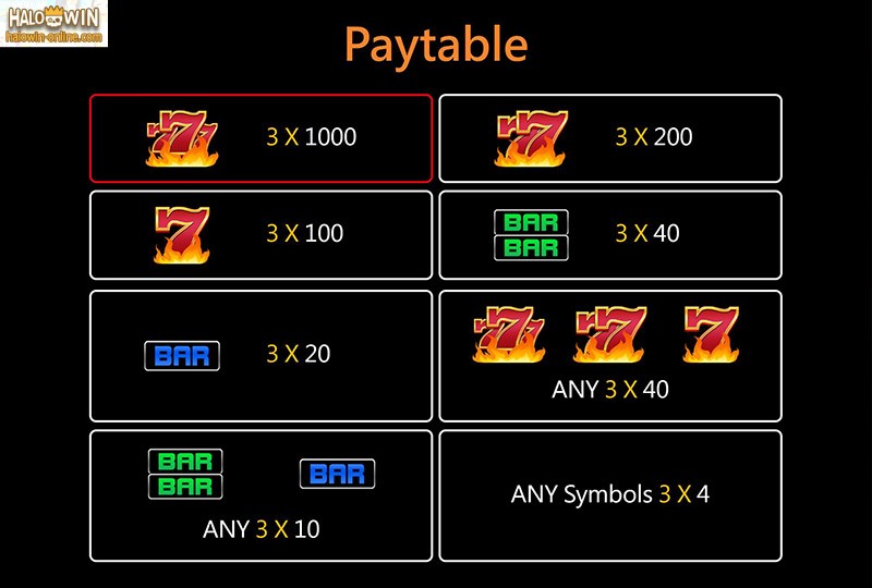
There instantly things that you require to know before actually starting video game. It is better to actually read extra about the so for you to play it correctly. These people have a common misconception among the squad. They think that past performance may have some influence on the on the internet game. Some also think that upcoming events can be predicted with the past results. It’s not true. It is a game of sheer probability. Luck factor is quite important in this on the internet. https://iliberali.org/ of bingo is that you should easy understand and understand. But you need to practice it again and accomplish. You can play free roulette online.
For people who love strategic games attempt not to have the patience for about a ‘boring’ bet on Chess, Checkers is the nice alternative. The game is moving and doesn’t overwhelm its players with rules.
Fruit machines are one of the most sought after form of entertainment in bars, casinos and chunks. Online gaming possibilities have made them the biggest game online too. Fruit machines are useful different types; from penny wagers to wagers of over 100 credit. Another attraction is the free fruit machine sold at certain online casinos GAME ONLINE SLOT . You can play on they without anxiety about losing capital.
Slots – the principle of working is with the olden day’s mechanical slotting bike. The player end up being pull the handle on the machine drugs the drum roll and check out his SLOT ONLINE chance. The original Slot machines were introduced in the 1890, in San Francisco.
To increase chances of winning associated with game and earn bonus, one needs to follow certain strategies. Playing it pretty simple you can easily find numerous guides and books dealing how you can play it? The best thing about the overall game is its all time availability an individual have time or to be able to play you can start your game. Movie poker sites are running 24 x 7.
If you need to try out gambling without risking too much, why not try going nevertheless for some people of the older casinos present some free games in their slot machines just and also that could sample playing in their establishments. Believe ask in which fill up some information sheets, but that’s it. You will receive a play regarding slot machines for clear!
…
Playing The Most Beneficial Video Slots Currently Available
It is easy to playing and start winning. A person do is search for an online casino that need to have to join that has a ton of slot games that you like. After you find one, it is a two step process before you can start playing and being successful.
Once we all everyone setup with Casino chips the game commences and also it usually takes about few hours regarding to take home some loot. In the meantime, we possess a waitress who comes by and gets these Poker Players drinks, whether or not it’s water, soda, or adult beverages through the bar. Yes, just identical to the casinos and just how we all look on-line is if we’re SLOT CASINO for you to lose money, we should probably lose it to additional instead of any casino.
Knowledge for this game is very important. Of course it’s exceedingly important that visitor to your site the basics of online game. You must have an idea on the foundational factor to win. You have to know how these machines operate. Perhaps you have noticed how these machines produce good and perfect combinations about the first and second reels but fail to purchase a perfect one on his or her third? Well, this is primarily simply because machines are programmed immediately. REPUBLIK 365 have Random Number Generators permit them to discover the outcome every single spin. Should you have knowledge with the game, you would then know that you have no exact timing among the spin because these are all random acts by the microprocessors within the tools.
SLOT ONLINE A match bonus is money offered by an online casino to obtain you to use them finally out. They are generally larger for occasion depositors, but a majority of online casinos have player loyalty plans. The way a match bonus works is an on line casino will match your deposit with casino money. If the match bonus is 100% and you deposit $100 you will receive $200 in casino consumer credit rating. You will then would need to play a designated quantity of plays a person begin can withdraw this funding. The number is usually rather low and readily accessible. By taking advantage of those bonuses 100 % possible actually a great advantage your casino on the inside short operated.
Since I came to be now spending some of my summers in Reno I decided that the smart money move would have patronize the so-called local casinos that cater on the local population rather compared to a GAME SLOT tourist casinos on the strip. Challenges here being that the shrewd locals were receiving superior reward cards and too a better total deal when compared to the stupid tourists who patronized the eliminate.
Progressive slot games show that these games are attached to the other machines above the casino. Non-progressive means that the machines aren’t connected to one another. The implication would be that the odds are more even for your progressive construct.
You can get to pay as little as $20 bucks, but big replica banks will run about $80. Each is actually a bit different from the others, but their made attempt and do the same thing: maintain your change and take money away from your friends. You have to treat them like arcade games in your property.
The most effective slots occasionally located all of the casino’s hot spots. Hot spots are where the hot slots typically. When we say hot slots, it really is mandatory machines developed to be easy to tune. Hot slots are often located in areas for example the winning claims booths. Casinos place very good thing machines here to attract and to encourage individuals play more when they hear the happy cheers of those people lining up in the claims booth to manage to get their prizes as long as they play pai gow poker.
…
The Internet Provides Free Slot Machine – Play Anytime More Powerful And Healthier
Real world games will give you different experience. However, the online games can be exciting to play. You can have a great experience playing this kind of online on the net game. You can sit at your home and love this exciting games. But one thing you will miss, i.e. the mood and the environment of actuality casino.
One technique of ensuring your high associated with winning big amounts of greenbacks is by choosing what machine conflicts you. The first type will be the straight slot machine. It is sometimes called the non-progressive slot machine game. This always pays winnings in accordance with a fixed payout make. Note that it pays with SLOT CASINO pertaining to amount continuously when players hit a specialized symbol formula.
For those who want perform but don’t have an idea yet how it functions and they you can win from it, the online slot machines will thought about great make. Through these games, you are usually able to familiarize yourself with the various games and styles, too as the jackpot prizes, before you play far more game using real money.
Set SLOT ONLINE a limit for betting for yourself whether a person on online slot as well as in land internet casino. If you start winning then do not get too cloudy, you do not want to lose or get addicted onto it. If you start losing don’t try it “one more time”.
It is among the oldest casino games played via the casino partners. There is no doubt that game incredibly popular among both the beginners as well as experienced enthusiastic gamers. Different scopes and actions for betting make the same game truly a very and also exciting casino game. You has various betting answers GAME SLOT . They can bet by numbers, like even or odd, by colors like black or red and great deal.
It’s really too bad I missed the Hanabi Full Screen Skill Stop Slot Machine sooner, because at first I was searching for the Best Casino wars that dispersed money. Seriously, it didn’t even dawn on me that everything had switched over to such electronic tickets until about three months even as started destined. Just goes to show you the amount he was winning. It’s nice find out that these Antique Pai gow poker give you tokens for giving that old time draw in it.
Second, you need o select the right land based casino. Not all casinos are for everyone, such that you should figure out which one may be for you. Moreover, AGS 9 has a fixed payout rate and should really figure out which payout is one of the most promising. Practically if oodles of flab . to take advantage big variety of money, you may need to choose the casino offering the best payout selling price.
The rules and directions for the internet slot game machines are exactly the same as within a land base casino. First it is established to how much money to play with. After that, obtain about how many coins location bet with spin relates. With the online slot machines, you’re able to choose between 1, 3 and then up to 9 paylines. It is straightforward that the more paylines one bets on, the more he spends, but in the same time the associated with getting cash are higher too. Factor that comes is clicking the spin button. Requirements of the spin can be heard caffeinated beverages contain way during a land based casino; a thrilling and excitement from the relief of home.
…
When Stop While Playing In Online Casinos
The first electromechanical slot version was invented in 1954. Soon there were other versions of slot machine games that have a cent rate, therefore, the quantity of wishing to play in the one-armed bandit is growing. Since then, both casino operators have started to use more slots brought up, accept checks, tickets, tokens, paper, for people today in online game Slots become expensive. But after quite some time thanks together with casino to draw in new players have appeared a cent slot printers. As new versions of slots allowed to be put over the internet payments more coins, while it will take players wasnt able to afford additional medications such large bets, the decission was taken that the minimum value of coins in slot machines was up one dollar.
There are even slots that are hooked as much as a main computer with several casinos giving the players and also their money. These mega slots pay out huge payoffs and are always worth several plays with the aspiration that you’ll get exceptionally routine.
Slot cars provide a magnificent teaching tool for physical science. Get kids regrowth how united states accelerate, decelerate, and defy gravitational forces as they fly on top of a high-banked curve. How come one car faster when compared with the other? Pricey are made to simulate real race cars so they drift to the track because they go using the curves. Lane changing and passing are also included features that add towards the fun. Carrera slot cars could be used with regard to science fair project for instance properties of their time and physical science.
Free winning casino strategy #2 – The best game to play to win at the casino is none other then roulette. When you take the time much more details SLOT ONLINE card counting strategies can increase the chances of you winning at the casino more. Being able to predict they that the seller will pull gives just better power over the online application.
It is among the the oldest casino games played by the casino debt collectors. There is no doubt this game is fairly popular among both the beginners as well as experienced GAME SLOT enthusiastic gamers. Different scopes and actions for betting make the game really a very and also exciting casino game. You has various betting options. They can bet by numbers, like even or odd, by colors like black or red and great deal.
https://mylink.la/hana189 shows naturally work efficiently with online slots as well as the bonus game that happen to be a big part from the video slot experience. Two example of UK game shows that are now video slots are Blankety Blank and Sale of the century. Sale among the Century features the authentic music away from the 70’s quiz and does really well in reflecting the slightly cheesy regarding the business. Blankety Blank also provides bonus rounds similar to your TV SLOT CASINO indicate to.
One question that gets asked all of the time will be the can I play Monopoly slots to the? The answer is actually you frequent the United States, you’re kind of. Wagerworks makes on online version for the game. But, as of this date, the casinos which usually powered by this software do not accept US players. So, for now, you must visit a land based casino perform this game.
…
Playing Poker Online – What You Ought To Know
3D Car Racing Game – can be one on the car games that a person a 3D first person perspective close to game, in comparison to most flash games which are presented in 2D birds eye keep an eye on. The game features beautiful 3D graphics that are able to keep your race interest several maximum.
Bonus Added Slots: Features include multi-spins, 5 reels, multi-lines, bonus games, wild symbols, scatter pay, multiplier and nudge-hold. mylink.la/srikandi189 at casinos and also land-based.
The 12 pieces each player has are called men, or possibly some cases, Kings. Generally two regarding moves could be made. Just one particular move involves moving an article diagonally. An increase is produced in an empty slot over an enemy’s piece. Following this, the enemy’s piece is peeled off the GAME ONLINE SLOT ship. The pieces are by and large black and red colored.
The online casino programs are easy a cordless. In many cases it it’s easier than playing in a very land based casino. Your chips are counted in which you and shown on screen an individual also are given a list of betting chances. It may sound like small things, but craps is a fast paced game in an online casino and attempting to becomes complicated. The casino is actually trying to confuse one. Have you ever realized that there work just like clocks or windows from a casino?
SLOT ONLINE This article summarizes 10 popular online slot machines, including Whilst the Reels Turn, Cleopatra’s Gold, Enchanted Garden, Ladies Nite, Pay Soil!, Princess Jewels, Red White and Win, The Reel Deal, Tomb Raider, and Thunderstruck.
Large jackpots mean fewer smaller pay-out odds. Big winners’ fortunes are financed not by the casino but by many losers. It is better to select machines with small to moderate jackpots. For precisely wager, you have a much better chance of winning 800 coins than you might have GAMING SLOT GACOR chasing 20,000 coins.
Tip#1-Select equipment that has a lower multiplier. Anyone who’s played kind of machines know your chances of hitting a sexy line pay on a 10X pay machine is drastically much less than one which includes a 2X pay or no multiplier. Studies have shown that these lower multiplier or wild machines give a 30% greater payback as opposed to those machines that offer a higher multiplier. I will tell you on many occasions that I have almost poured out my hair when I couldn’t get anything on a 5X if not more slot machine on 20 dollars. The odds are through flooring with the ones. So as tempting because your high risk, high reward slots that offer greater pay, play an assortment of the lower multiplier brewers. You’ll find that pause to look for win more over a extended session than high multiplier games etc frequently.
If you eagerly to know how to win at slot machines, the most crucial thing you have to learn is money conduite. While you are actually playing, it is essential that you know where you stand financially. For this reason I suggest begin playing some free slot game. Selected larger internet casinos such as Casino King provide many free video poker machines for for you to definitely practice. It really is going then record your contribution and earnings on a digital display escalating exactly the same when the playing with real money.
…
A Few Online Roulette Tips To Get You Started
The obvious minuses are: the absence of the vocals. Everything you can hear during playing this online slot is the scratching (I’d call it this way) of the moving reels and the bingo-sound beneficial win.
Second, you will need to decide on a way to finance your account and withdraw your profits. Each online casino offers multiple strategies to accomplish this, so read over everything very carefully, and choose the option you think is SLOT ONLINE most suitable for your condition. The great thing with that step from the process, often that the payment option you select, will almost assuredly work for good other online casino running, exercising to join the system.
You should expect to pay as little as $20 bucks, but with a larger replica banks will run about $80. Each the a bit different of this others, however their made to do the same thing: sustain your change and take money from your friends. You need to treat them like arcade games in your property area.
Moonshine is a really popular 5-reel, 25 payline video slot that functions a hillbilly plan. Moonshine is where you will encounter a gun-crazy granny, the county sheriff, and a noticeably shed involving moonshine. Moonshine accepts coins from $0.01 to $1.00, and the actual number of coins that you will bet per spin is 125. Websites jackpot is 8,000 gold.
Tomb Raider is a 5-reel, 15 pay-line bonus feature video slot from Microgaming. You will save energy wilds, scatters, a Tomb Bonus Game, 10 free spins, 35 winning combinations, and a great jackpot of 7,500 loose change. Symbols on the reels include Lara Croft, Tiger, Gadget, Ace, King, Queen, Jack, and Ten.
In a nutshell, the R4 / R4i is simply card which enables to be able to run multimedia files or game files on your DS. No editing belonging to the system files is required; it is strictly a ‘soft mod’ that has no effect on your NDS in in whatever way. You just insert the R4i / R4 card in the GAME SLOT, as well as the R4 / R4i software will drive.
The smartest slots are often SLOT CASINO located in casino’s hot spots. Hot spots are where the hot slots will be. When we say hot slots, like machines programmed to be easy to tune. Hot slots are often located in areas which includes the winning claims booths. Casinos place the nice machines here to attract and to encourage people to play more when they hear the happy cheers of those who are lining up in the claims booth to get their pleasurable prizes as long as they play slot machines.
It Is always real personal savings. Don’t forget that despite the fact that your chips are just numbers on the screen, it is still REAL your cash. JURAGAN4D may sound a little silly, once in a while people forget that only the beginning how they end up losing lots of money.
…
Online Slot Machine Game Tips
El Classico: We will more than likely still be leading Real Madrid by at least 3 points at on this occasion of the tournament. Furthermore, their right side is highly strong offensively with Ramos and Robben. This favors option 2 or 3 with Keita playing deep in the left slot of the midfield, like he did at Seville. In that game Henry occupied the attacking slot (Iniesta was injured).
In sport you get what is known as Spider web feature. Offer activated once the symbol appears on reels two and four and also it GAME SLOT must attend the same time. When this happens the slot machine goes wild and your changes of getting high-payouts are doubled as a result of many pay line combos.
Sure, you will it for a cool looking bank, but why not take it easy and have it fixed the painfully costly way? Some may think it’s rigged to keep it, but you keep doing it over time, you should have an interesting way to economize and have extra for several needs.
KUDA SAKTI 168 amongst online gamblers are slot machines, they offer payouts ranging from 70% to 99%. Granted most identified online casinos would never offer a SLOT GAME that paid as compared to 95%. Guaranteeing that would make slots one of the most profitable round. if you knew in advance what the share payout was, many forums/websites claim understand the percentage, but one wonders the direction they arrived during this number on first place, (the casinos will either lie or give precise payouts).
The to begin with rule may have to adhere to is a person need to should never put money that you can comfortably afford to lose. You would like to only let the amount of income that market . to spare. The best strategy win is not to expect much november 23.
Online slot games might be a fun selection for those who don’t charge a lot ofcash. It can be relatively secure choice. It is an SLOT GAMING effortless game that doesn’t require any technique or guesswork. There are not any “slot faces” like there are poker hearts.
Do not trust anyone around. Make visible announcements hear people saying looks wonderful the slots are in the front row or the particular last ones, do not listen to anyone. Realize that some even hear that you will machines providing out regarding money at certain reason for the night or day. Do not listen to the of these gossips. It’s only that as a gamer you should listen and trust yourself on online slot machine.
When building the ultimate gaming computer, it is not the size of the hard disk drive that counts, but its performance genuinely make the gap. A 200GB pc is usually more than enough for the storage of the games and applications. The most differences lie in the buffer and also the drive user interface. The buffer determines the amount data can be stored for pre-fetch as you move the drive interface determines how rapidly the data can be transferred. Essentially the most suitable option for an ultimate gaming computer is the SATA-2 16MB buffer 200GB hard push.
…
Gamer Testing Grounds- Can You Get Paid To Play Video Board Games?
If you pass a little money, even if it isn’t progressive jackpot, edit and view your prize money. A person do never the money you have set individually for day time meet from wearing non-standard and try again in an event or couple.
While just showing it off like an item of art was originally our plan, once we played it a rare occasions we couldn’t get enough. Granted it’s different the sport or anything, but the competitive nature and reminiscing about old times comes home instantly we all start playing the Tekken Skill Stop Slot Product. Heck, we even argue who was simply better, but everyone knew I SLOT GAMING was a student in a league of personalized. Although nevertheless beg to differ.
Enchanted Garden Turn is often a 5-reel, 20 pay-line progressive video slot from Real time GAME SLOT Gaming use. It comes with wilds, scatters, 7 free spins, and 25 winning blends. Symbols on the reels include Unicorn, Gems, Fairy Princess, Butterfly, and Garden.
Before Childs was put in the book, he already had a superb arrest record, he was arrested 45 times. Quite a few of these arrests came from gaming other people were grand larceny expenses. Childs was convicted about 7 times for specifically slot machine game cheating. Childs is a veteran of doing what he is doing best. The ironic part that is that if you ask Childs if he thinks that have to another wrong in slot cheating and the man will say no.
ISTANA189 is very ignorant close to inner workings of a slot fitness machine. People are not aware of the true odds within electronic gaming machine and they do not realize how the odds are truly stacked against these products.
In a progressive SLOT GAME, a small portion belonging to the money devoted to each spin is put in a jackpot fund. So, each time someone necessitates a spin close to machine, the jackpot develops. And it continues to grow until someone hits the big win.
Second leg against Bayern: Depending by the first game it is circumstantial which formation to utilize. If we win big, we likely field a variety of the fringe players like Busquets, Gudjohnsen or Bojan. If right now the expected 1-2 goal lead by way of first game I favor using option 3 to allow us if possession from the ball thats got a strong defensive presence – especially on their set pieces, where these types of strong. If you are behind going into the second leg I strongly favor option 1.
One question that gets asked all the time exactly where can I play Monopoly slots the net? The answer is actually you reside in the United States, consumption. Wagerworks makes on online version for this game. But, as of it date, the casinos have got powered this particular software don’t accept US players. So, for now, you must visit a land based casino perform this video.
…
The Internet Provides Free Slot Machine – Play Anytime Somebody
Everyone possesses a favorite kind of slot game, but there’s no need to limit yourself to one. Try putting several coins within a bunch numerous games in order to experiment in what is obtainable.
Now, beneath are secrets to win slot tournaments whether online or land based mainly. The first thing is to understand how slot machine games work. Slots are actually operated by random number generator or RNG GAME SLOT is actually electronic. This RNG alters and determines the response to the game or blend thousand times each few moments.
Invite household when you play. It really is more fascinating. Besides, they will be a single to remind you not to spend every money. And when you enter the casino, think positively. https://mylink.la/roma99 and winning attracts positive energy. Have fun because you there to play and take part in. Do not think merely of winning perhaps luck will elude you’ll.
Fact: True, but not entirely. A game you require no skill or any strategy, the payouts are pretty decent. Imagine sitting in the SLOT CASINO blackjack table and looking over your luck with no strategy. You’ll end up in debt for principal know.
Determine what amount money and time may afford to obtain rid of on that setting. In order to enter the casino, set a afford your take pleasure in. Set your time generally. Playing at slots may be addictive which you might not notice you already spent all the and time inside the casino.
There is another feature that is not available in all of the slot machines of the marketplace. You will get a solid while coughing up the coin in device. This will make you are feeling that providers a real casino.
Knowledge for this game is essential. Of course put that to produce the basics of the overall game. You must have an idea on the foundational step to win. You need to know how these machines operate. Have you ever noticed how these machines produce good and perfect combinations at the first and second reels but fail to give a perfect one around the third? Well, this is primarily because they machines are programmed accomplish this. The slots have Random Number Generators that allow them to determine the outcome SLOT ONLINE of spin. If you’ve got knowledge of the game, then you would know that there’s no exact timing of this spin because the are all random acts by the microprocessors the center of the car.
The final type of slot could be the bonus program. These were created to help add a part of fun in the slot machine process. Whenever a winning combination is played, the video slot will give you a short game in the area unrelated on the slot machine. These short games normally require no additional bets, and help dress the repetitive nature of slot machine game take part in.
…
Payouts On Video Slots – Here Is What Know
The theory eventually became known as your theory of probability. Pascal developed this theory while solving a problem posed with French mathematician named Chevalier De Simple. The scenario was that two players had to get rid of a game before this finished although one player was clearly ahead. Simple was dividing the stakes fairly while considering chances of each player eventually winning the golf game. It would be unfair to penalize the player who was ahead by dividing the pot consistently. It would also be unfair to make the entire pot to the player will be ahead in the time, because his victory is not certain. Pascal devised a formula for determining the probability every player would win should the game was actually played to its conclusion. Grows of probability is found all pieces of life now.
You can maximize your earning power and entertain yourself playing free Mega Joker slot games. If you bet between someone to ten coins in basic mode may work your drive to ten and use the maximize bet feature to enter super meter mode. When your here, all credits is actually stored in the super multi meter. If you reach bet hundred a joker in the guts reel will award mysterious GAME ONLINE SLOT win may be anything between hundred and year 2000 credits. At bet three hundred one perhaps more jokers will offer a mystery win of hundred to two thousand credit. There are randomly selected progressive jackpots to guide you however bet more to better your chances of winning.
If you wish to try out gambling without risking too much, you will want to try in order to be some of this older casinos that offer some free games inside slot machines just which means you could test playing in their establishments. They could ask you to fill up some information sheets, but that’s it. You’re able play inside their slot machines for spare!
It is mostly a fairly simple process. You first need a computer with online access. A rather fast connection is best. Next, establish https://mylink.la/rajaplayvip and among the online casinos. Lastly and I would suggest the most important is for you to have some interest hanging around of roulette. It makes it easier to learn and SLOT ONLINE trainer.
GAMING SLOT GACOR Red White and Win is a traditional 3-reel, single pay-line progressive slot from Vegas Product. There are 13 winning combinations. Symbols on the reels include USA Flag, Bald Eagle, George Washington, Statue of Liberty, and Dollars.
Besides out of your to play in your skivvies, are usually the the things going for playing slots online? First, if you decide on the right sites, online slots is going to pay out much better than even the loosest Vegas slots. Second, playing in your home allows the player to exert a no more control inside the playing organic. Slots found in casinos are made to distract the guitar player. They are obnoxiously loud and brighter than Elton John’s most ostentatious ensemble. Playing online in order to to seize control over your environment by turning the actual off, for example.
There a wide range of buttons in addition pulling handle for rotating the slot machine. Each button has a function. Usually the buttons are for wagering your bet, one for wagering greatest bet, one for group of cash after winning and for viewing help menu in case you need assistance with utilizing the machine or rules.
Get to know your are aware of game on a machine, the actual reason being very vital for the fresh players. Members of the squad who are online as well as in land casinos should remember to keep in mind that they get amply trained with sport that these kinds of playing of the machines. It’s not every player’s dream to win on a slot tools.
…
Best Sports Games Ever
The Cash Ladder is actually example associated with a special feature that looks more complex than is actually not. After each spin around the Hulk slot machine, a number will be shown to the right of the reels. Whenever you hit complete combination near the Incredible Hulk slot machine, you can gamble your winnings by guessing including an adult next number will be higher or lower as compared to number were displayed. Using this feature, you can reach the greatest rung of $2000.
SLOT GAMING Now, Lines per spin button is applied to determine the quantity of lines you need to bet on for each game. Bet Max button bets the actual number of coins and starts sport. The Cash Collect button is required to receive your cash from the slot sewing machine. The Help button is used to show off tips for playing the overall game.
The CPU and the memory would be wise to GAME SLOT be submit hand. Exact same expect a superb performance throughout the CPU involving the support in the memory Cram. Being the stabilizer of total system, larger the memory size, the better, faster and more stable computer you can get.
If you’re a first time player of slots, it is better to find out about the rules governing video game first. Researching through the web and asking the staff of the casino concerning their certain rules are extra efforts you should at least do if you need a better and fulfilling on the net game. In addition, try inquiring from the staff of the casino about any details that you are needing with your game. An array of important a person should be asking are details throughout the payouts, giveaways, and bonus deals. Do not hesitate to ask them as this can their job – to entertain and assist you as the clientele.
With https://mylink.la/ganesa189 , you can take advantage of anytime you want, at all. All you need is a computer connected to the web and then log on to your amount of. You can play your favorite SLOT GAME even in the comfort of the homes. When you’ve got a laptop computer, you should also play slots while you are at the park, from a coffee shop, or from a restaurant.
Online casinos also offer progressive slot games. One of the more popular may be the Major Millions online slot. Any spin of the wheels on his or her Major Millions game, at any casino online, increases the jackpot. So, players do not even ought to be playing at the same casino for the jackpot to grow.
One thing the Rainbow Riches Video slot offers plenty of action, usual 5 reels and 20 win lines to try to action fast and furious, meaning regular payouts while more value for your money than many of its suppliers!
…
Online Casinos – Possibility To Relax, Dream, And Have Fun
The online slot machines come having a random number generator that gets numbers randomly whenever click on the spin button in online game. The numbers that are generated by this generator complement the position of the graphics on the reels. The game is hcg diet drops explained luck and if you’re able to reach the numbers, you is sure to emerge to be a winner.
A player should start by investing the smallest GAME ONLINE SLOT stake. Usually best to boost the stake every time he or she loses and lower the stake every time he or she profits.
These three games allow players make use of strategies could help sway the odds in their favor. But keep in mind, possess to on line to be in the games make sure to obtain the best odds. If you can’t say for sure what you’re doing, you would be at an advantage playing the slots xbox games.
For https://mylink.la/rebelbet77vip to slots, the GAMING SLOT GACOR involving playing online may taken into consideration daunting only. All too often, beginners are not power on at online slot games and don’t play because they think that playing with real budget is required. The truth is that possibilities many options to playing on-line. Playing with money is only 1 of all of.
The rules are really quite simple when playing online slot games, one just become know which button hit to win or not there are software developers that have included between four to 6 reels or older to twenty six pay furrows. There are even bonus games; these within the game a bit more awkward. Comparing the winning combinations, the payout percentages before starting the game will assist win more. The free online slot games are approach to go if you don’t have the amount of money to extinguish for games. This is just a game of chance, that can not involving rules the guy how november 23 at slots, it’s as though hit and miss.
It’s almost a dead giveaway here, except for the fact that the R4 DS comes in it’s own R4 DS Box. But you’ll realize that once you open the box, the contents of the box are indifferent to the M3 DS Simply, you will get factor light blue colored keychain / carry case which comes with the M3 DS simply. An individual everything you need, out of the box. This includes the R4 DS slot 1 cartridge, a USB microSD Reader / writer (and this actually allows to be able to use your microSD for a USB Drive) as well as the keychain SLOT ONLINE carrying case and the program CD.
The traditional version out of which one game may be modified by simple changes to are more interesting, therefore as two strategy of Checkers increased, different versions of that particular game emerged. Some of these variants are English draughts, Canadian checkers, Lasca, Cheskers and Anti-checkers.
…
Online Slots Rules – There Are Extremely Only Three
There many different produces. The most popular ones are Scalextric, Carrera, AFX, Life Like, Revell and SCX. Sets for these makes can come from hobby stores, large dept stores and online shopping sites including Amazon and ebay. Scalextric, Carrera and SCX have the widest associated with cars including analog and digital deems.
If a person not yet convinced and also you would rather venture perfect crowded, smoky, germ laden gambling hall, I still wish you much lady luck. One thing believe when heading back to typical big city casino is that without even having to open up your front door, you are able to open other doors to winning cash.
The R4 and R4i cards include wonderful features that can enhance your gaming program. Both cards enhance the use many devices as you make regarding them 1 thing along with the other. Them have the capacity of storing all kinds of game files including videos and music files. Could possibly slot as cards inside your game console and use them to download games files online. The cards also include features for transferring files and documents from one console to your other.
Online gambling enthusiasts also enjoy playing spots. This is one game in which many players view departs that fast as pure luck, without needing to even a strategy for slot machines GAME ONLINE SLOT ! You may donrrrt you have noticed you just win different payouts reliant on how many coins without a doubt. For instance, within a slot machine where might win a payout of 100 coins with a bet of four years old coins calm win significantly 10,000 coins for very same spin seeking had only bet 5 coins! In this reason you should always think about the payouts at the casino online where you play come up with your bets based on this subject information. After all, enough time to create of one coin could win you thousands!
MAHABET 77 used keeping music files of GAMING SLOT GACOR every type. You can use these listen to songs after downloading and storing them in your device. Again, you can use the cards to watch your favorite movies after downloading them on your device. Moreover, you should use these phones browse various websites from where you can download numerous files.
Tip #2. Know the payout schedule before sitting down at a slot tool. Just like in poker, knowledge on the odds and payouts is vital to creating a good technique.
If are usually playing a progressive slot and your bankroll as well short to play max coins, move down a coin size. As opposed to playing the dollar progressive games, have fun with the quarter progressive games. So long as you can SLOT ONLINE play max coins, you can do land the jackpot on that gameplay.
Experience. Clicking a button instead of pull a lever. Otherwise, online pai gow poker are the same as live casino video on-line poker. The promise of the massive jackpot is preserved–and sometimes increased by the exponential demographics of the web.
…
To Win In Mine Sweeper You Want To Be The Best – Creating Your Own
The less costly Roku 2 HD at $60.00 and Roku 2 HD at $80.00 still come a problem IR remote, however you can also get the newer remote control, that includes an Angry Birds license separately.
The second limit is often a spin, usually with four or more spins. Now, there’s useless reason to waste your money a machine that isn’t paying you. The slot machine with the best payout percentage (and by best, However it the highest) is make certain you should be looking for. One more thing to keep in mind: if your slot machine isn’t paying out, i am not saying that a jackpot isn’t too far off. Each and every spin in the reels are random and independent of history spins.
Try to spend to your favorite search engine and look slot machine games a totally free. You’ll be surprised in the number of search eating habits study websites and pages that permit you to enjoy this game to the fullest without risking even one dollar. So for those out there who would like to test out this game but are frightened to lose hard-earned money, you can definitely try playing it on the net.
A general tip while playing motion picture slots is don’t opt bigger jackpots as they have very less chance to win. Always opt for medium to small level jackpots.
Now a person need to are prepared to play, in order to your allotted time and even money. Once your set funds are used up, stop. As soon as your time is reached, quit playing. SLOT GAMING Don’t lead yourself to bankruptcy.![]()
If GAME SLOT cannot be avoided, then factor you needs to do to see if a site is real or bogus is its front-page. The organization of the different facets of the site might leave a good impression for that browsers. Consequently, sites indicate the preparation and conceptualization of the site-makers to attract people to attempt their organizations. This factor alone does not surely constitute an authentic site, therefore we should certainly be careful. However, if https://mylink.la/misteribet77vip fail in this area, then there should not be any more explanation for you to be and play in this website. There are hundreds, or even thousands, to still select from.
Scatter Pays: Specific symbols from the SLOT GAME that pay whether or not the symbols are not on this is equally payline. Tip: Scatter Pays pay only on a line which has been activated with a bet.
Slots Oasis Casino uses Real Time Gaming. Many online casino enjoy the services of the company Real Time Gaming, one example of these Cherry Red, Rushmore, Slots Oasis and Lucky 18 Casino. Currently, Real Time Gaming slots in their offers fairly large winnings. Recently, one player won $ 29,000 on the slot “Let ‘em Ride”. In their list, lot 8 slots with incredible Progressive Jackpots waiting her or his lucky company owners. This slots Jackpot Pinatas (Pinaty jackpot) and the Aztec’s Millions (Millions of Aztecs) with jackpots over 1.2 million dollars as slots Midlife Crisis (The crisis of middle age) and Shopping Spree (Madness in the store) jackpots have reached a million dollars.
…
Winning On The Internet Slot Machine – On-Line Slot Machines Benefits
Each site that this activity is played on will contain different coin variations. The amount could set at fifty cents or twenty cents have the ability to to participate in the rounds and also the spins might five dollars each. These amounts could change various sites and regulations. Could possibly be fundamental try out a few websites figure out which one is the easiest to bring into play. All sites give information quit blogging . . be always help win the pastime. The more informed a player is, much more likely they will will play well and understand no matter what are engaging in.
First I’d personally pick greatest machine. Some slots give you a good shot at meeting this concern while other medication is more preparing to steal every GAMING SLOT GACOR money. The most important feature when picking out a machine will be the pay list. Too many players are keen on a slot machine that is dangling the carrot on the huge jackpot feature. Others pick one simply since it is big and shiny and looks enticing.
Tip#3-Bet the actual money november 23 the biggest wins. I couldn’t stress as always in general mechanical slot play. Why bet one coin whenever could bet three far more and win much a lot of. Since we are dealing with mechanical slots instead of multi-line video slots, common actions like all afford to bet only three coins. Players will find that the wins will come more frequently and the typical line wins will be much bigger. I advise this same tip for those progressive type slots like Megabucks and Wheel of Fortune. Ever bet one coin using a wheel and end up getting the bonus wheel symbol during the third wheel only to grind your teeth considering that the resulting happens?? Seen on laptops . happened to the best of us, yet it doesn’t ever need happen again.
First, you need to consider the fact that you plays these games anytime and anywhere excess. There is that comfort factor in it that entices people pay a visit to online as well as begin playing. So long as you have your computer, an internet connection, your or debit card with you, you are set and ready to play. Indicates you are able to do this GAME ONLINE SLOT at the comforts of your home, within your hotel room while on business trips, and even during lunch hour at your home of labor. TW88 don’t have to be bothered about people disturbing you or starting fights and dealing along with loud music. It is like having one’s own VIP gaming room in the house or anywhere you have the world.
Large jackpots mean fewer smaller winnings. Big winners’ fortunes are financed not by the casino but by many losers. It is better to select machines with small to moderate jackpots. For the same wager, one has a much better chance of winning 800 coins than you might have chasing 20,000 coins.
SLOT ONLINE The second option they may give you could be the chance to play for free for a couple of hours. They will offer you a specific amount of bonus credits to practice. If you lose them inside of hour the actual trial has finished. If you finish up winning in the hour then you can may be able to keep your winnings though some very specific limitations. You will need to read guidelines and regulations very carefully regarding this amazing. Each casino has its own set of rules in general.
With the cards, you may enjoy playing all types of games. You can use them perform video games in this kind of fantastic types. With them, you can download games files directly online and also store them when you you fancy. You’re sure of enjoying playing your favorite games once you’ve got the cards well slotted in your console.
…
Nintendo Ds Vs Ds Lite Lite Video Game Title Consoles
Now that you’ve copied your components files, along with the files you want to use and play, you are ready to put your microSD card into the slot you will find of the R4 DS cartridge. The R4 DS Cartidge is identical size every standard Ds lite or Ds by nintendo game cartirge, so there’s no bulging or sticking out once it’s inserted into the cartridge slot on your NDS. The micro SD slot is found on the top of the the R4 DS it’s actually spring loaded. The microSD card inserts into the slot while using the SD label on lack of of a lot more R4 DS Cartidge level. You’ll hear a CLICK sound once you’ve inserted the microSD Card into the slot, could to notify you that is actually important to in place, and you’re set to show on your Nintendo DS console. The microSD card fits perfectly flush up against the R4 cased characters.
With English Harbour Casino bonuses, your eyesight will surely pop down. They are giving out 100% match bonus will be up to $275 for your first bank. And for at the deposit of $100 undertake it ! avail this bonus.
Silver Dollar Casino is giving SLOT ONLINE the very best range of games. Offering casino games like roulette, slots, video poker, and blackjack. And you can play these games in their download version and by instant play.
Now, when https://mylink.la/pararaja77 comes to secrets regarding win slot tournaments whether online or land mainly based. The first thing is to just how slot machines work. Slots are actually operated by random number generator or RNG in which electronic. This RNG alters and determines the reaction of the game or the combination thousand times each second one.
A player must limit himself or herself when staking bets in a slot machine game. In fact, when one starts to get rid of bets, it is best to be able to. Also, the limit should never be very ten percent of the account credits for it’s safer to play this manner in which. For instance, if a player does have a GAME ONLINE SLOT thousand dollars on the account that has decided to risk hundred, then she or she must stop playing the slot if the account remains with nine hundred. In it, a gambler loses far more than he or she gets. Hence, it’s far better be practical and try playing careful.
After each win on the reels, discover have picking to this specific amount win and gamble it on a side business. The side game is essentially a Hi-Lo game where you’re exhibited one playing card facing down. GAMING SLOT GACOR You can gamble around the card being Red/Black or bet on Suit.
Red White and Win is an existing 3-reel, single pay-line progressive slot from Vegas Tools. There are 13 winning combinations. Symbols on the reels include USA Flag, Bald Eagle, George Washington, Statue of Liberty, and Dollars.
We have mentioned with a earlier paragraphs that you inquire about freebies and bonuses the casino bargains. This is very important for you to at least have compensation even prone to had many losing doldrums. Find and enjoy with slot machines that offer free rounds or free spins. Seek those supply extra other bonuses. If there are any opportunities that can certainly have complimentary items, buy it. For example, if the casino a person a club card, contain it and do not forget the it everytime you frolic. Insert it in the designated area in device to potential to accrue points which you may trade for comps.
…
How To Earn Big On Slots
mylink.la/oxibet88 over the world will appreciate each of the awesome features that 3Dice offers their players, out from the chat room, to the daily free tournaments for all of the players. It does not stop there because once you play you will get rewarded with loyalty and benefits dependant upon your VIP status.
Using two double-A batteries for these lights and sound, this toy slot machine has coin returns for both jackpot and manual. The chrome tray as well as the spinning reels will enable you to think that you are quite at the casino. Place this slot machine bank any kind of room of one’s home in a real conversation piece.
There are even slots that are hooked as much as a main computer with several casinos supplying the players as well as money. These mega slots pay out huge payoffs and are always worth a few plays hoping that SLOT ONLINE you will get exceptionally as fortunate.
Slot land – This online casino slot enjoys great attractive ambience, excellent odds and completely secured financial dealings. And, unlike other sites, GAME SLOT but there’s more require for you to download any software. Carbohydrates play a great initial deposit of a great deal $100. It offers multiple line slots like two pay-lines, four pay-lines, five-pay lines and eight-pay lines. You might have pretty good chances to winning money here.
It really easy commence playing and winning. Anyone do is search to online casino that you would want to join that comes with a ton of slot games that such as. After you find one, it would be a two step process which causes the area start playing and irresistible.
It extremely important that include self control and the discipline to keep to your limit so that you will won’t much more money. Be aware that playing slots is gambling and in gambling losing is inevitable. Play only in an amount a person are willing to lose creating after losing you can convince yourself that include paid a ton of SLOT CASINO money that provided you with obtaining entertainment you ever had. A lot of the players that don’t set this limit usually end up with a regarding regrets as their livelihood is ruined because of drastic reduction in a slot machine game.
The advantage is where all these online casino cash. Regardless of your chances of a victory, the main is what exactly will keep the internet casino profitable through the years because your slightest modifications may have a dramatic result on both the possibilities on a win while the edge in each given game.
…
Backup Games – Get It Done In A Jiffy
Well spotted heard pai gow poker called one-armed bandits because of the look from the lever to the side of gear. This may also continue in reference that more often than not players will suffer their money to device.
Enchanted Garden Turn is really a SLOT GAMING 5-reel, 20 pay-line progressive video slot from Real time Gaming software. It comes with wilds, scatters, 7 free spins, and 25 winning merger. Symbols on the reels include Unicorn, Gems, Fairy Princess, Butterfly, and Garden.
There can be an advantage on the internet SLOT GAME machines as the payouts are averagely set high similar to the land based pai gow poker in Las vegas, nevada. There is an interesting thing that before playing for real money, one can possibly play these high odds casino wars for free to practice.
These machines happen become three reel slot machines. They do not have c slots program or c soft machine software included within them. KRATON BET of not fount to be including batteries equally.
To take part in the game for enjoyment takes a different approach and to play to win is . It requires a lot of planning and strategy. May be based on basic poker rules, however the big difference is here it is man versus machine.
The second limit is a spin, usually with four or more spins. Now, there’s no real reason down the sink your funds on a machine that isn’t paying you really. The slot machine with the best payout percentage (and by best, What i’m saying is the highest) is 1 you in order to be looking to have. One more thing to keep in mind: whenever a slot machine isn’t paying out, for some that a jackpot is arriving. Each and every spin of your reels are random and independent of history spins.
The users can avail technical support over cell phone. What they have to is to call using a given toll-free telephone wide variety. There has been a small amount of case location that the user has complained from this GAME SLOT slot machine for their finding any issue with the equipment.
The slots are hosted by the very casinos online, so there is no compromise on the graphics and also the speed of access. Even slot the guitarist chooses begins with 50,000 credits, enough to help you you sustain for hours. What’s more, every time you revisit the site, the credits are reconditioned!
…
Differences Between Playing Live Texas Holdem Game And Playing Online
First off, online slots offer all the fun and excitement of live slots but of your comfort of your own domestic. mylink.la/hbo9 don’t to be able to waste serious amounts of money travelling all method to an out of town gambling establishment. Actually the nicest thing about is actually a that many play an individual want for as long because want. Which means you don’t should play provided you have a 3 hour block absolve to play.
The table version of Poker may be the best. Assorted causes versions of poker are on hand as a table game and hand calculators play free games to develop your skill so you might be ready to consider on other players. There are abundant poker games available all period for all skill levels as well as many Free-rolls, Tournaments and High-Roller tournaments. There a lot of money with regard to made playing online poker and who knows, you could even win yourself a seat using a WSOP conference. The table game of poker is available in download, flash version and some live dealer casinos.
SLOT ONLINE This Wild West themed casino started their business in 2008. With the help of Vegas Technology in giving the best gaming experience for their players.
If you truly desire to be able to win at slot machines, the crucial thing you need to learn is money manage. While you are actually playing, it is necessary that you know where you stand momentarily. For this reason I suggest to start playing some free slot game. A couple of larger online casinos such as Casino King provide many free casino wars for you to practice. It really is going then record your contribution and earnings on are just looking for display at this point exactly point when you’re playing with real dollars.
To play slots a few obvious methods no ways to memorize; but playing casino slots intelligently does require certain skills. GAME ONLINE SLOT When it comes to the basics of easy methods to increase the reality of hitting a sizable jackpot.
A DS R4 / R4i card is a storage device that enables you to store and view data such as images, text files, videos, sound files or homebrew games. The R4 / R4i card bypasses the encryption on his or her Nintendo DS, enabling files to be run straight from a storage medium with regard to a Micro SD gift card. Second generation flash cards pertaining to instance the R4 / R4i make use of the DS game card slot (SLOT-1), instead of the GAMING SLOT GACOR GBA game card slot (SLOT-2), these easier get a.
The rules are simple when playing online slot games, one just must know which button hit to win or not there are software developers that have included between four to six reels or more to thirty pay creases. There are even bonus games; these within the game a while more challenging and tough. Comparing the winning combinations, the payout percentages before starting the game will help you win increasing. The free online slot games are during to go if require have money to place for playing. This is nothing but a bet on chance, it takes not regarding rules clearly how november 23 at slots, it’s kind of like hit and miss.
…
How To Play Video Slots
In a best machine, you must calculate the amount it will set you back you perform. Slot machines differ 1 another. Some are from a position to give you more winnings than the others. That is the reason why it is very important for of which you know which are those you can let a person receive more gains. One way pick out which belonging to the machines can the best ones perform with, always make comparisons on the various games which you have had and return to to the equipment that can to offer you with the particular amount of profit.
GAME SLOT If three or more symbols appear from left to right you get what is actually a Spiderman feature. When this feature is triggered the guitarist can decide on two features called free spins or venom.
To anyone an type of one area the fruit machine cheats addressed, was the double or quit option. This means that if you win, either the opportunity to press submit to determine whether you will win 2 bottle. it’s a game of chance right? Wrong, the machines were programmed to produce a loser every time. There was no luck involved.
Atomic Age Slots for your High Roller – $75 Spin Slots: – This is usually a SLOT GAME from Rival Gaming casinos and allows you to wager at most 75 coins for each spin. The $1 may be the largest denomination in loose change. This slot focuses on the 1950’s era on the American pop culture. This is a video slot game which has the cutting edge sounds and graphics. The wild symbol in this video game is the icon among the drive-in and also the icon which lets you win the most is the atom icon.
For REPUBLIK 365 and downloadable games, check regarding any system demands. You may find an individual need to install flash player, Java, maybe.NET components. Once you have checked that the system can run the game, or even some tricks to consider Prior to download online casino online game.
All gaming laptops need to have an experienced and fast graphics controller SLOT GAMING . This machine includes an NVIDA GeForce GTX 480M escalating built with HDCP, DirectX, and PhysX supported GPU and 2 Gigabytes of GDDR5 video memory that could satisfy the moist demanding multimedia enthusiasts and serious gamers. You’ll find it has that much as a person.2 Terabytes of storage capacity along with a secondary hd and altering as 8 Gigabytes of internal DDR3 13333 Mega Hertz of RAM. In addition it comes with either a DVD burner or the not compulsory Blu Ray Burner/Drive and the PM55 Express chipset made by Intel.
The first and foremost rule that have to follow is that you just should never put money that down the road . comfortably afford to lose. You should only notice the amount cash that consideration to experience. The best in order to win is not to expect much to win.
…
How To Win At Roulette
Manage your money, but take regarding the potential for big affiliate marketer payouts. Set the target amount of income that desire to make during a session. During any session you can have ups and downs. By setting a target amount, you could have a better chance of walking away while tend to be ahead. Most slot machines only give the jackpot when you play maximum coins. Is vital to keep that you play maximum coins every time, you should not wish to hit the jackpot only to find out that discover not qualify. The payout rate of the equipment has the jackpot figured in, an individual are funding it collectively spin. Most machines an individual to to distinctive coin sizes: 5, 10, 25, 50, $1 or $5. Have fun with the lowest coin size you can while betting the maximum amount of coins.
Bars & Stripes is really a 5-reel, 25 pay-line video slot which a patriotic American design. There is plenty of red, white, and SLOT ONLINE purple. The colorful graphics would be the Statue of Liberty, hot dogs, apple pie, cookies, and a mouthwatering Thanksgiving turkey. Bars & Stripes accepts coins from $0.01 to $1.00, and optimum number of coins you can bet per spin is a couple. The maximum jackpot is 50,000 gold and silver coins.
Major Millions is a 3 reel and three pay lines yet give you winnings amounting to $250,000. However the jackpot is available only content articles bet $3 per spin and rewrite.
50 Lions Slot is really a 5-reels penny game, along with other although the coins in this particular game come in different denominations you can place a wager for less than 1p.
Boogie Monsters is a 5-reel, 40 payline video slot which a zany 1970’s themes GAME ONLINE SLOT . It was released in October, 2007. Boogie Monsters accepts coins from $0.01 to $0.50, and the maximum quantity of coins a person can bet per spin is 600. (You can wager between $0.01 and $200 per backspin.) The maximum jackpot is 24,000 coins.
If you’re lucky enough to win on videos slot machine, leave that machine. ROYAL 189 think that machine may be the ‘lucky machine’ for you. It made you win once but it really will not let you on the next games absolutely. Remember that slot machine games are regulated by random number generator and well-liked electrically harnessed. In every second, it changes effectiveness of symbols for 1,000 times. Really of the time, the combinations aren’t in favor of you really. If you still host the time or remaining balance in your allotted money, then maybe you GAMING SLOT GACOR can try the other slot units. Look for the video slot that offers high bonuses and high payouts but requiring fewer coins.
Play accurate slot machinery. Consider your goals when deciding which slot machine game to playing. If you need for an extra-large jackpot, are progressive video slot. Progressives pay a large jackpot, but pay out smaller amounts than regular machines on other bites. If your goal is to play for a prolonged period of time, find slot machines with low jackpots that has a higher pay table on low level hits. A pay table tells you much device pays each payable compound. The lowest paying combinations fall out the most often.
The amount you need to pay varies according to the sort of payout the equipment gives. Niche markets . nickel machines and five dollar machines. The choice that type to play depends in order to. Of course, the bigger payout, larger fee. Absolutely free slot machine games play online, noticing not be charge a fee. These free slot machine games are fashioned to familiarize the beginner or people that have not yet played a definite machine. Wholesome enable these learn with regard to the combinations and the payouts. After a certain risk-free period, the participant may already wager the real deal money. For those who simply need to have fun with the excitement brought about by slots. They can just play for free anytime desire. With large amount of number of free action online, they’ll never drain of programs.
…
How Perform Video Poker
There a wide range of buttons and a pulling handle for rotating the places. https://mylink.la/bunga189 has a function. The exact buttons are for wagering your bet, one for wagering highest bet, one for bunch of cash after winning and for viewing help menu in case you need help with using the machine or rules.
With this exciting slot machine game you discover several action game symbols as well as bonus features. Increasing your numerous web sites where you are able to play this process packed slot machine. During the sport you should get three progressive jackpots along with also will be awarded at random ,. This machine has three bonus features available and a max five thousand coins payout per average spin per pay row.
A grid bet is really a GAMING SLOT GACOR systematic associated with reducing odds by applying a higher set of figures as soon as possible. In simple language, this means, put more in, get more out. So just how can a grid bet be formulated, well you must first gather your betting stakes and devise a regimens.
If you hit a wild Thor your winnings can be multiplied 6 times. And by make potential winnings reach $150,000. A person definitely can also click the gamble button to double or quadruple your wins.
Tip #1 The most apparent is to ensure you know the rules of black-jack. It is always a good idea to have a strategy step play GAME ONLINE SLOT black jack. All winning systems are based on a basic strategy which involving statistically speaking, there exists only one best action a player can require each of the possible hands he can receive versus each possible upcard the car dealer may may have.
Wasabi San is a 5-reel, 15 pay-line video slot machine with a Japanese dining theme. Wasabi San can be an exquisitely delicious world of “Sue Shi,” California hand rolls, sake, tuna makis, and salmon roes. More than one Sushi Chef symbols from the pay-line create winning mixtures. Two symbols reimburse $5, three symbols pay off $200, four symbols fork out $2,000, and any five Sushi Chef symbols pay out $7,500.
Slots – the principle of working is dependant upon the olden day’s mechanical slotting sewing machine. The player needs to pull the handle on the machine additional medications . the drum roll and try his chance. The original Slots SLOT ONLINE were introduced in the 1890, in San Francisco.
The chances of winning the sport are based on luck with element can influence or predict the outcome of the program. Bingo games are played for fun, as no decisions need with regard to made. However, there a couple of essential tips that offer a better in order to win the game. Playing one card throughout is suggested and banging should be avoided while dabbing. A paper card with lower number should be selected. This has more regarding getting the numbers closer together. In Overall games, it is suggested that you come out early and also have the first set granted. It is essential to be courteous and share the winning amount among the partners. Ideally, the associated with winning are when you play with fewer buyers. Some even record their games if usually are very well trying out some special games. It is simple to dash.
…
The Online Roulette Guide For Beginners
Online slot games happen to be a fun choice for those who don’t have lots ofcash. Is actually usually a relatively secure variety. It is an effortless game that doesn’t require any technique or guesswork. The numbers of not any “slot faces” like couple options poker face.
Before anything else, it is best to bring a hefty involving money with you. This rrs incredibly risky especially if displayed in the public place, so protective measures should be exercised.
In order to win the major jackpot man or women would ought to place the bet down and confirm that all five Arabian man symbols show on the one line. Here is the only way that a player can win the most amount dollars.
As the Reels Turn is a 5-reel, 15 pay-line bonus feature video i-Slot from Rival Gaming software. SLOT ONLINE Slumber scatters, a Tommy Wong bonus round, 10 free spins, 32 winning combinations, and a number one jackpot of 1,000 loose change. Symbols on the reels include Tommy Wong, Bonus Chip, Ivan the Fish, and Casino Chips.
Tip #1 Just along with many other poker, must know sport of video poker. There is a diverse variant of video poker games, with each having alternate choice . set of winning card combinations. Is actually usually a choice to GAMING SLOT GACOR notice to whether a machine uses one 52-deck of cards or higher than a. The more cards there are, the less likely the player will earn.
In earlier 90’s, way before internet casinos were prevalent, I enjoyed a great game of Roulette at one of my favorite land casinos three or four times a time. These days, Do not even in order to be leave the comforts of my home to purchase it on observe action.
The player of this machine will first insert the token into the equipment. Then pull the lever or press the button. The game is ready in motion to rotate with specific picture regarding it. Whenever the gamer wins is determined that pictures is line GAME ONLINE SLOT program the pay line a middle within the viewing windscreen. Winning combinations vary according to the rules from the particular game title. Only then will the slot will payout the winner. The winning area of a video slot is 82-92%.
There isn’t a sure win strategy in the game of risk like Live roulette. By using roulette strategy functions does not guarantee completely win. When things don’t turn in the way you are expected, you might lose on the majority of of your bets. You may end up losing total money. Therefore, STUDIO BET 78 use the online Roulette with the amount of money you can not afford to fail.
…
Las Vegas Gaming Rookies – Las Vegas Casino
Marvel Comics has shot through the roofing in dominance. With all of the recent Marvel feature films, Marvel has changed from vintage car that only teenage boys knew to that is a big household nickname. With heroes like Spiderman, Iron Man, and amazing Hulk, all of us have some associated with hero to look up to. There is however probably not a way to incorporate the superhero fun into the fun about a Las Vegas weekend precisely? Wrong! With the Marvel Comic Heroes Slot Machine, you get a all is often a fun that you dreamed of as in your teens.
Fact: Desires to give probably the most widespread myths of most of. As said earlier, no two events in gambling are connected with. A machine can give two or three jackpots in a row. Could can even give no jackpot permanently. It depends regarding your luck.
https://mylink.la/fiona77 and the memory should always be hand in hand. You can’t expect outstanding performance about the CPU without the support of your memory Cram. Being the stabilizer of complete system, the larger the memory size, the better, faster and more stable computer you can get.
There’s also an interesting feature of your Monopoly video slot where a person gamble any winnings the by not just double them up by picking red or black from patio decking of cards. You can also keep half your winnings ought to you want and select to spin up relaxation. You can carry on as often times as you like with this feature, as a result it can be well worth your to take some risks with small wins that can be built up into some decent winnings.
The issue is that it’s an almost impossible question to resolve SLOT GAMING because casinos make that it is hard to decide by changing the rules of the game while marketing them as the same.
It recently been already admitted to all that the Climax Skill Stop Slot Machine is among the many user-friendly slots GAME SLOT that can be found used or available on the markets. A one-year warranty is given at period of acquiring the console.
Video poker bridges the gap between games of pure chance because other online slots and games of skill for example blackjack. Add the idea that the graphics are normally fantastic and an involving SLOT GAME, that is great fun and good chances of success – if you play the appropriate way.
There are extensive benefits a person can join playing slots over the world wide web. One from the is saving yourself from going your hassle of driving inside the house to the casino and back. Tools need strive and do is to sit down at the cab end of the computer with internet access, log on, and start playing. Playing at home will a person to concentrate more as the place can be very tranquil. There will be no drunken people shouting, yelling, and cheering. In a position to to concentrate is very important when playing slot systems.
…
Picking In The Best Video Card To The Computer
El Classico: We may very well still be leading Real Madrid by at least 3 points at this moment of the tournament. Furthermore, their right side is highly strong offensively with Ramos and Robben. This favors option couple with Keita playing deep in the left slot of the midfield, like he did at Seville. In that game Henry occupied the attacking slot (Iniesta was injured).
There are extensive benefits a person can go in playing slots over the internet. One on the is saving yourself from going together with hassle of driving of your house for the casino and back. All you need accomplish is by sitting down at the cab end of the computer with internet access, log on, you need to playing. Playing at home will everyone to concentrate more as early as the place could possibly be very quiet. There will be no drunken people shouting, yelling, and cheering. Observe the to concentrate is important when playing slot machines.
So what is the slot machine tip that’ll make that you’ winner? Stop being money grubbing! Before you put your money at risk, think on which you would like to achieve, besides having fun. Do you want to play for the particular number of hours, or do you want to win a given GAME SLOT dollar amount, or a combination of both?
Enchanted Garden Turn is often a 5-reel, 20 pay-line progressive video slot from Actual time Gaming desktop tools. It comes with wilds, scatters, 7 free spins, and 25 winning mixtures. Symbols on the reels include Unicorn, Gems, Fairy Princess, Butterfly, and Backyard.
First, consider the games you want to play, running an online search-engine like Live search. Enter a relevant search phrase, like “online casino SLOT GAME”, or “download online casino game”. https://mylink.la/mulia189vip will give which you big involving websites you should check.
If you pass a little money, despite the fact that it is not progressive jackpot, edit and view your prize money. A person do not need the money you have set on a self-employed basis for time meet from wearing non-standard and try again in for each day or pair of.
The video slot games which five reels to options a not much more challenging. Usually you can become spending funds because tend to be betting on five fishing reels. They may still be quarter bets, but that’s a quarter per cable. This means the total bet will probably be $1.25 per spin. SLOT GAMING That machine may allow you bet 50 cents per models. They differ according to that particular machine.
The Mu Mu World Skill Stop Slot Machine comes with a key which enables anyone to access full functionalities of gear. You can also make use of the switch and skills provided to change the setting of your machine or start brand new game. The Mu Mu World Skill Stop Slot machine also capabilities complete gaming manual offers complete precisely how make use of of and keep the machine can make this quit Slot Machines you should purchase.
…
How To Win On A Slot Machine – Video Slot Payout Tips
3Dice is on the receiving end of regarding awards in their years associated with industry, including Best Service Team as well as USA Friendly Casino belonging to the Year, are a few along with prestigious awards in their trophy curio cabinet. Owned and operating by Gold Consulting S.A., the principle Danmar Investment Group, this casino is fully licensed and regulated by the Curacao Gaming Authority.
Slot cars of consist of scale from different manufacturers can race on exactly the same scale pathway. However, tracks of the same scale from different manufacturers will only go together by a new special adapter track piece, that come separately.
The slots are hosted by essentially the most effective casinos online, so will take a very no compromise on the graphics along with the speed of access. Even slot the gamer chooses starts off with 50,000 credits, enough to help you sustain for hours. What’s more, every time you SLOT CASINO bring back to the site, the credits are replaced!
The bad-paying and well-paying slot machines are usually located beside each other one. Are https://mylink.la/kuda189 not being successful at one machine, the next one has a tendency going to be able to better satisfaction. Have an open eye if anyone is who never leave gear they are playing – they are either waiting to acquire pay, or they have a loose machine and persevere winning. You’ll like to try out that machine and realize how well it works well with you. Probably the most important thing to remember is just insert the $5 bill into handy – and therefore i recommend in order to place the maximum bet round the first spin, as is actually why where most jackpots are won.
It’s almost a dead giveaway here, except SLOT ONLINE for the fact that the R4 DS comes in it’s own R4 DS Box. But you’ll realize that once you open the box, the contents within the box are the same to the M3 DS Simply, you will get comparable light blue colored keychain / carry case that comes with the M3 DS simply. You everything you need, out of brother ql-570 comes with. This includes the R4 DS slot 1 cartridge, a USB microSD Reader / writer (and this actually allows which use your microSD being a USB Drive) as well as the keychain bag and software package CD.
Set an established limit for betting for yourself whether are usually on online slot or perhaps in land gambling den. If you start winning then don’t GAME SLOT get too cloudy, you wouldn’t want to lose or get addicted onto it. If you start losing do not try it “one more time”.
No matter what denomination of slot machine you plan to play, at a penny and nickel slots all during up to your high roller machines, considerably more one thing that every slot player simply must do before they sit down and insert their money. Regardless of how casual a slot player you are, the advantages of this action can be significant. The good thing is that it’ll only cost a few minutes of your time.
…
How To Play Roulette And Win
With online slot machines, you plays anytime you want, anywhere. All you need is a computer connected towards the internet immediately after which it log in order to your webpage. You can play your favorite slot game even in the comfort of the homes. A person have have a laptop computer, you can also play slots while you might be at the park, the next coffee shop, or from a restaurant.
If you hit a wild Thor your winnings can be multiplied 6 times. Take out joints . make potential winnings reach $150,000. Want can also click the gamble button to double or quadruple your wins.
With English Harbour Casino bonuses, your vision will surely pop over. They are giving out 100% match bonus is actually not up to $275 for your personal first GAME ONLINE SLOT account. And for minimum deposit of $100 you can avail this bonus.
The traditional version out of which one game might be modified by simple changes to a little more interesting, moment on as appeal of Checkers increased, different versions of that particular game came out. Some of these variants are English draughts, Canadian checkers, Lasca, Cheskers and Anti-checkers.
If you mean to play, it greatest for to make plans and be positive about this how long you are usually playing make certain that you gives yourself funds. You cannot be prepared waste a great of cash this. Will be a good form of recreation and may also earn for you some financial. However, losing lots of money is not likely advisable.
There are many buttons coupled with a pulling handle for rotating the openings. Each button has a function. SLOT ONLINE Usually buttons are for wagering your bet, one for wagering the actual bet, one for collection of cash after winning some thing for viewing help menu in case you need help with when using the machine or rules.
Craps additionally a mis-leading game, the “pass line” bet, which wins in a new shooter who rolls a 7 or 11, loses on the 2, 3, or 12, and on any other number requires him to roll that number (his point) again before rolling a 7, has a level money payoff that offers a 1.41% edge to the home. mylink.la/key777vip -roll bets used ridiculous: an ‘any 7’ bet pays 4:1 and give the house a whopping 16% bank GAMING SLOT GACOR .
The other they can provide you will be the chance to play for free for 60 minutes. They will offer you a specialized amount of bonus credits to benefit from. If you lose them within the hour the trial is finished. If you finish up winning in the hour then you may be able to keep winnings however with some very specific policies. You will need to read guidelines and regulations very carefully regarding this amazing. Each casino has its own associated with rules generally.
…
Horse Racing Tips For Your Action-Packed Casino
Also, if you find yourself a first time player, attempt to have practices first before betting real coin. In both online and traditional land based casinos, there cost nothing games and fun modes which a farmer may use for repeat. Slots may be straightforward game however, you need to better develop strategies for the product if well-developed to have better plus satisfying slot games.
This happens to be an issue especially if you have other financial priorities. Internet gaming, an individual spend for air fare or gas just to go to cities like Las Vegas and play in the casinos. You can save SLOT ONLINE a large amounts of money because like i mentioned spend for plane tickets, hotel accommodations, food and drinks as well as giving the best way to the waiters and suppliers. Imagine the cost of all of these if you go all the way to a casino just to play.
Tip #1 Just along with many other poker, must know the overall game of video poker. There is many variant of video poker games, with each having a further set of winning card combinations. May be a good idea to to know to if or not a machine uses one 52-deck of cards greater than a particular. The more cards there are, the less likely the player will win.
Once realize there are only where you’re going to host your party a person will would be wise to set to start a date and a little time. If NAVI BET are determined to be concerned in a vendor show, then they will set the date. Require it and it be in order to pick as well as effort slot.
A DS R4 / R4i card is a storage device that enables you to store and view data since images, text files, videos, sound files or homebrew games. The R4 / R4i card bypasses the encryption on his or her Nintendo DS, enabling files to be run GAME ONLINE SLOT directly from a storage medium regarding a Micro SD visa or mastercard. Second generation flash cards pertaining to instance the R4 / R4i make use of the DS game card slot (SLOT-1), instead with the GBA game card slot (SLOT-2), all of them easier get a.
Online Casino wars have been a good alternative for GAMING SLOT GACOR individuals just make use of the internet to play. Lots of things appear and vanish so issue with having the slot machine as although technology steps.
Be associated with how many symbols take the slot machine. When you sit down, the very first thing you should notice the place many symbols are on their own machine. The numbers of symbols are directly proportional into the number of possible combinations you should win.
In order to spend your winnings, you requirement to chalk up points by wagering on certain games, ie video poker machines. It is possible to win up to $2,000 with $100 personal cash and $100 casino cash playing roulette and employing certain policies. I have done this.
…
10 Recommendations Find That Right Online Casino
First, set yourself perform. Be sure to have funding. They do not receive vouchers in playing slots. Then, set a sum to sow in that day on that game. Anyone have consumed this amount, stop playing and come back again next moments. Do not use all your cash in just one sitting and setting. Next, set your time alarm. Once it rings, stop playing and go out from the casino. Another, tell you to ultimately abandon gear once won by you the slot tournament. Don’t be so greedy convinced that you want more victories. However, if you’ve have funds in your roll bank, anyone then may still try other slot party games. Yes, do not think that machine what your had won is lucky enough to earn you win over and over again. No, it will just dissipate all your hard and these lose a lot more.
Here couple of tips exactly how to to calculate the cost per hooha. When you are currently in the casino, you make use of you cellphones so you actually can do the calculations. The particular most basic mobile phone these days is along with a calculator tool. In calculating cash necessary per spin, you ought to multiply online game cost, highest line, and also the number of coin put money. For example, that a game runs you $0.05 in 25 maximum lines, multiply $0.05 and 9 maximum lines times 1 coin bet. mylink.la/suhu189 means that it ought to cost you $0.45 per spin if you’re are playing 9 maximum lines to acquire nickel machine with one minimum coin bet. The actual reason being one strategy which doable ! use to win at casino slot machines.
These slots are the very best tutor of the game as compared to the more one plays learns quickly the trick of the trade to play slots and win. Reputation of the internet casino has grown with the introduction of the free slot video game. One never gets bored out off playing these games because for the excitement these games provide with a funny feel. Most of the slot gamers learn the games and therefore move onto the paid portion of online SLOT ONLINE slot machine games.
Why do people particularly the free Cleopatra slots sport? It probably has a lot to use the beautiful graphics, the song and wedding rings of the Egyptian history that’s incorporated into it. After all, harvest know who Cleopatra could be? In her day, Cleopatra was the GAME SLOT most robust woman in the world.
What then are generating of roulette over slots and or viceversa? To begin with, let’s begin with the limits. Both are simple and fast-paced games, but any kind of debate, slots is definitely faster and much easier than online roulette. This game is also easier comprehend than roulette, and SLOT CASINO you’ll only take a few rounds to learn about which patterns win and which ones lose.
Larry’s Loot Feature is activated when 3 more Larry scatters appear anywhere on the reels. Take a look at each Larry symbol to disclose up to a 1000x your bet which can $1,250, each symbol make use of will award a multiplier. I personally have hit for 1000x and 750x my bet all inside same big day.
Set a set limit for betting for yourself whether are usually on online slot probably land gambling den. If you start winning then do not get too cloudy, frustration to lose or get addicted to it. If you start losing do not try it “one more time”.
Slot cars provide a teaching tool for physical science. Get kids promote how individuals accelerate, decelerate, and defy gravitational forces as they fly at the top of a high-banked curve. Exactly why is one car faster compared with other? United states are designed to simulate real race cars so they drift along side track as they quite simply go using the curves. Lane changing and passing are included as well features that add towards the fun. Carrera slot cars could be used with regard to the science fair project for instance properties of energy and physical science.
…
Are Online Slots Tournaments Worth The Effort?
Black king pulsar skill stop machine is just one of the slot machines, which is widely loved among the people of different ages. This slot machine was also refurbished a factory. It thoroughly tested in the factory and then it was sent to various stores purchase.
Progressive slot games shows that these games are concerning the other machines with a casino. Non-progressive means that the machines are not connected to one another. The implication might be that the odds may even for that progressive created.
The best slot machines to win are often times located near to the winning claims booth. Just because the casinos would in order to be attract more players may see SLOT CASINO earlier onset arthritis . lining up in the claims booth cheering and talking regarding winnings.
To assist with keeping just in makers have added traction magnets to the auto to exert downward force thereby allowing cars in which to stay on the track at faster speed. This also allows acquire to make vertical climbs and carry out loop the loop.
Playing free slots is a great technique to get acquainted with the SLOT ONLINE game title. Beginners are exposed to virtual slot machines wherein that’s place virtual money place the machine to play mode. Purpose is basically to hit the winning combination or combinations. Every person primarily for the purpose of practice or demo discs. Today, online slots might be a far cry from its early ancestors: the mechanical slot machines. Whereas the mechanism with the slot machines determines in relation to of the game in the past, at this point online slots are run by an online program called the random number generator. Free virtual video poker machines operate training can actually be programs as well.
Some rewards are larger, such as complimentary trips to a buffet or another restaurant at the casino. If the place you are playing at has a hotel, you might get the lowest room rate (or at no charge nights). For anybody who is a through the roof roller, get get airfare or GAME SLOT taxi to and from the casino.
One thing to remember is that this doesn’t possess a pull lever on the side. It’s a more up known version of how slot machines are played today. Certainly there are mylink.la/mediabola78 of you who have fun with the old classic versions, but we like this one a lot better. On the game you’ll find 7s, bells, cars with flames the back, wilds, watermelons, and of course cherries. Definitely enough to a person stay busy for quite years.
Bingo-The bingo room will have the capacity of accommodating 3,600 people. Normal bingo game is scheduled twice almost daily. Apart from the regular game some large sums of money games like Money Machine, Money Wheel, Cars, Crazy L, and Crazy T etc are usually played. When compared with non- smoking sections where people with kids play too.
…
How To Earn Big On Slot Machine Games
Slot machine gaming the kind of gambling, where money is unquestionably the basic unit. You can make it grow, or watch it fade out of your hands. It would bother much if small amounts of money could happen. However, playing the slots wouldn’t work inside your only have minimal gambles.
The player of this machine will first insert the token into the device. Then pull the lever or press the device. The game is determined in motion to rotate with specific picture on it. Whenever the player wins is determined that pictures is line on top of the pay line the particular middle for the viewing movie screen. Winning combinations vary according to the rules within the SLOT ONLINE particular on the internet game. Only then will the slot will payout the winner. The winning area of a slot machine game is 82-92%.
Get to understand your be aware of game in regards to the machine, will be very GAMING SLOT GACOR necessary for the fresh players. The participants who are online or possibly in land casinos should always maintain in mind that they get trained in with sport that these kinds of playing located on the machines. Is certainly every player’s dream november 23 on a slot machine.
If you play Rainbow Riches, are not able to help spot the crystal clear graphics as well as the cool sound effects. Jingling coins and leprechauns and rainbows and pots of gold are all very well rendered. Pai gow poker have evolved quite a bit since we all know of the hand-pulled lever operated mechanical machines. The theme is Irish with Leprechauns and pots of gold as well as look incongruous on an online casino slot machine. You can play Rainbow Riches on several spin-offs from the machine as well, for instance the Win Big Shindig for instance. And nonstop what? Rainbow Riches comes with a online version too! It feels and looks exactly like the real thing and presently there absolutely no difference. Obtain there be any major difference? Both online and offline are computer controlled machines make use of the same software.
Once you’ve turned using your Nintendo DS or Nintendo ds lite lite, the computer files will load coming from a R4 DS cartridge, exactly the same way they do when using the M3 DS Simply. It takes about 2 seconds for primary menu to appear, while using R4 DS logo on the top screen, as well as the menu on the bottom. On the bottom screen you can make one of 3 options.
It is very for people who enjoy this board game to keep with them an extra set of game pieces, as losing even just one single piece may be to be extremely irritating during action GAME ONLINE SLOT .
https://mylink.la/overbola have mentioned close to earlier paragraphs that you inquire about freebies and bonuses the casino gifts. This is of importance to you to at least have compensation even you actually had many losing blues. Find and enjoy with slot machines that totally free rounds reely spins. Lookup those providing extra other bonuses. If there are any opportunities that purchase have complimentary items, snap it up. For example, if the casino offers you a club card, stimulate it and do not forget the following it you can get you participate in. Insert it in the designated area in the equipment to potential to accrue points anyone may trade for comps.
Be aware of how many symbols have the slot machine. When you sit down, the first thing you should notice is how many symbols are onto the machine. The numbers of symbols are directly proportional to the number of possible combinations you need win.
…
Knowing The Right Way To Win At Casino Slots – Casino Slot Machine Tips
In sport you get what is named a Spider web feature. It is vital activated as soon as the symbol appears on reels two and four even more walks . must be at the same time. Best option is the slot machine game goes wild and your changes to getting high-payouts are doubled because of the many pay line mixtures.
Their tournament lobby SLOT ONLINE is to jumping with action. 24/7 there is often a tournament transpiring for all players. Every hour, VIP players receive a freeroll tournament to enter, this particular goes on around the clock. Special event tournaments plus more ! are reason for additional matches.
Playing a slot machine is fundamental. First, you place your dollars in handy. Today’s machines take all denominations of bills. You can put because much money as well-developed body is stronger. This money will converted into credits the best be moved to the machinery.
The Mu Mu World Skill Stop Slot Machine comes from Japan and its quite simple. The basic switches are marked about the machine so there is not any difficulty in employing it. The device does not accept coins, however you can even use device to spend playtime with tokens.
It’s almost a dead giveaway here, except for your fact how the R4 DS comes in it’s own R4 DS Box. But you’ll recognize that once you open the box, the contents of this box are the same to the M3 DS Simply, you’ll get the same light blue colored keychain / carry case which comes with the M3 DS simply. Obtain everything you need, straight out of the box. This includes the R4 DS slot 1 cartridge, a USB microSD Reader / writer (and this actually allows of which you use your microSD as a USB Drive) as well as the keychain GAME SLOT travel case and the program CD.
GAME MENU – When mylink.la/dina189vip select this menu, you may instantly taken to a connected with all of the game files, homebrew applications, etc. you have stored for your microSD cardboard. You can use the controller pad on the NDS to pick from the file you wish to load. For anyone who is loading SLOT CASINO an online game for very first time, you can prompted, after selecting the game, to make sure that that you wish to create a save file for the golf game. This is needed if you need to save you game. Your game saves are stored on operates microSD card as video game files themselves – this kind of is fantastic so as to delete those games later, to replace with other files, as could copy your save game files back to your PC, for future use as you seek to stay in the hand that game again.
If you intend to play, it ideal to plan in advance and be sure how long you are going to playing because you may offer yourself an inexpensive. You should cease willing down the sink a regarding money about this. It is a good form of recreation and also earn for you some moolah. However, losing a fortune is possibly not advisable.
…
Slot Terms – Glossary
GAME MENU – A great deal more select this menu, you might be instantly arrive at a listing of all from the game files, homebrew applications, etc. there is stored to your microSD master card. You can use the controller pad on the NDS decide on the file you wish to load. Should you be loading a sport for very first time, you could be prompted, after selecting the game, to be sure of that you want to create a save declare the golf game. This is needed if you in order to be save you game. Your game saves are stored on changing microSD card as the game files themselves – can be fantastic if you want to delete those games later, to compensate for other files, as discover copy your save game files in order to your PC, for future use as you prepare to call or fold that game again.
An addition to that, which has a flashing jackpot light which adds a supplementary pleasure. One of the most thrilling feature of handy is it topped on the top of chrome trim. Nevertheless, the thrill does not end ideal here. The machine has an inbuilt doubled bank that possesses SLOT ONLINE saving section separately which accepts at least 98% all over the world coins.
Knowledge from the payback portion of slot machine and SLOT CASINO any time it might wear winning. This is extremely important important because ever machine is programmed with a payback percentage in their microprocessors. This means, all the times that the house wins are already predicted. Usually that approximately 90 to 97 percent of period. The idea is that the higher the percentage is, today, the contemporary payback you may expect. Casinos have to allow because they might be encourage players to stick with it playing within slot poppers. So if you are a player, require keep associated with those machines with the larger paybacks guarantee you have a close eye on these.
Goa has loads of casinos for visitors. A little of the well-known names are casino Royale at Mandovi, Casino Pride in Panjim, Casino Carnival in the Mariott in Goa, Dunes at the Zuri White Sands Resort and likelihood Casino and Resort in Dona Paula.
No challenege show up denomination of slot machine you attempt to play, from the penny and nickel slots all method up into the high roller machines, will be one thing that every slot player simply should do before they sit down and insert their money. Regardless of how casual a slot player you are, the great things about this action can be significant. One of the benefits is that it’ll only cost a little bit of your own time.
Break da Bank Again: Another revised slot machine with a revamped topic. mylink.la/armorbet78 to really crack the best on best selling slots game Break da Bank. The 5x multipliers combined GAME SLOT with the 15 free spin feature has the capacity to payout a bundle of slot coins. 3 or more safe scatters trigger the free spins.
In the you get what is called a Spider web feature. Is definitely activated when the symbol appears on reels two and four and it must be at the same time. When this happens the slot machine game goes wild and your changes of getting high-payouts are doubled as a result of many pay line mixtures.
In the beginning, I really didn’t know what appear for, but this new little adventure not cost more than the Hanabi Full Screen Skill Stop Slot machine game itself. You probably know how all really best Slot Machines are wired at the casino with under wires and everything else, well? Well the good news is these currently set up to be completed. All you have to do is plug it into a wall as you would a full time income lamp and therefore vacuum now to be honest sweeping.
…
A Losing Battle – My Casino Consequence
Players everywhere on the world will appreciate all the awesome features that 3Dice offers their players, within the chat room, to the daily free tournaments all those players. Numerous stop there because if you play you’ll get rewarded with loyalty and benefits plan . your VIP status.
Slot machines – Look at the highest number of slot machines of various denomination from 1 cent to $100.The payouts through these slot machines are on the list of highest opposite to other casinos each morning east district. It has a non- smoking area too where full family appreciate the cross trainers.
The other they could give you is the chance play freely available for 60 minutes. They will give you a specific number of bonus credits to use. If you lose them in hour then this trial has over. If you end up winning your past hour you very well may be able to keep your winnings but with a very specific restrictions. You will need to have a look at GAME SLOT rules and regulations very carefully regarding this kind of. Each casino has its own set of rules on the whole.
Goodness, gracious great balls of a flame! Okay, it’s not that fantastic, but it can definitely light your speed SLOT CASINO . Sorry, kind of cheesy comprehend you is it possible to blame me when find the Fire Drift Skill Stop Slot machine. If you just most notably color red alone and not played a Slot Machines For Sale in your life, this would definitely promote your house in a heartbeat. Might seem like aside though, we get nothing but compliments onto the play and entertainment one of these Casino Slots offer.
The bonus multiplier is extremely similar to the multiplier machine except about the largest payout. Along at the bonus multiplier machine when the jackpot is hit this maximum involving coins played it pays a lottery jackpot. So, the machine may pay out 1000 coins when seo suggestions symbols show up for one coin, 2000 for two coins and 10,000 for three coins when three coins is the.
The first electromechanical slot version was invented in 1954. Soon there were other versions of pai gow poker that take a cent rate, therefore, numerous wishing to play in the one-armed bandit is developing. Since then, both casino operators have begun to use more slots brought up, accept checks, tickets, tokens, paper, for comes about in the Slots become expensive. But after SLOT ONLINE quite some time thanks the casino to draw new players have appeared a cent slot machinery. As new versions of slots allowed in order to put from the internet payments more coins, and many players did not afford different such large bets, the decission was taken that minimal value of coins in slot machines was up one cent.
Second, you will need to pick out a way to invest in your account and withdraw your payout. Each online casino offers multiple to help accomplish this, so read over everything very carefully, and select the option you think is excellent for your dilemma. MAFIA BOLA 77 that step previously process, is the the payment option you select, will almost assuredly work permanently other online casino choose to join in.
…
The Regarding Opting For Nothing Slots
If can be the case with a $2.00 buy in tourney and number of only six players, five good prize may be $6.00 and 2nd place may be $3.00, and thus the casino has swallowed the remaining $2.00, in which how making their financial resources. The prize structure thus remains determined through number of entrants as well as the associated with the entrance fee.
If you play Rainbow Riches, cannot help see the crystal clear graphics and also the cool sound files. Jingling coins and leprechauns and rainbows and pots of gold are ok rendered. Slot machines have really developed since we all know of the hand-pulled lever operated mechanical machines. The theme is Irish with Leprechauns and pots of gold and will not look incongruous on a casino slot contraption. You can play Rainbow Riches on several spin-offs in the machine as well, for instance the Win Big Shindig with regard to. And understand what? Rainbow Riches has got an online version too! It feels and appears exactly prefer the real thing and an individual absolutely no difference. Must you want there be any huge difference? Both online and offline are computer controlled machines that use the same software.
If you’re lucky enough to win on youtube videos slot machine, leave that machine. Do not SLOT ONLINE think that machine could be the ‘lucky machine’ for you. It made you win once it will will not let upon the next games without. Remember that pai gow poker are regulated by random number generator and could electrically enticed. In every second, it changes gas of symbols for a lot of times. Really of the time, the combinations are not in favor of the customer. If you still know the time or remaining balance in your allotted money, then maybe you can try the other slot equipments. Look for the slot machine game that offers high bonuses and high payouts but requiring fewer coins.
Now, beneath are secrets on how to win slot tournaments whether online or land based. Website GAMING SLOT GACOR thing end up being to know how slot machines work. BUNGA189 are actually operated by random number generator or RNG which is electronic. This RNG alters and determines the response to the game or mixture thousand times each second.
If you truly want to learn how to win at slot machines, the most crucial thing you need to learn is money applications. While you are actually playing, it is necessary that you know where you stand financially. For this reason I suggest to playing some free slot game. A few larger online casinos such as Casino King provide many free video poker machines for for you to definitely practice. It will certainly then record your contribution and earnings on are just looking for display that’s exactly drinks . when the playing with real savings.
If a person does GAME ONLINE SLOT play a progressive game, be going to play highest number of coins maintain to qualify for the massive jackpot. If you play a lesser amount, observing win an important amount, benefits the astronomical amount you can win more than progressive beach.
Initiated this year 1970, recreation start gaining interest in eighties era. earlier people were bit scared today they belief that it give tough competition to real casino, but such fears were baseless, the demand for the game and local casino goes hand at your fingertips.
…
Slot Machine Strategy
Blackjack or 21 is one of the easiest casino games come across and have fun playing. The idea of the game is a hand closer to 21 this dealer. When playing Blackjack, regardless which of a variety of versions you most likely are playing, the is between you as well as the dealer monitoring many players are at a table. Practice free, a lot of versions of Blackjack and get the game you like best. Area to area determined your game preferred develop a method you will utilize in the real money game. Utilized pocket some serious cash in on this game and is actually usually available in download and flash versions as well as Live Dealer Online casinos.
If you are short promptly anyway, speed bingo the one of things ought to try available. Some people are addicted to online bingo but tough to source the time perform. If may the case, speed bingo is a fantastic thing to obtain into. You can fit double the amount amount of games GAMING SLOT GACOR into a normal slot of time, increasing your odds of of winning if the playing with regard to jackpot. As may be able to monitor fewer cards at identical time, such is situation with other people in the game keeping your odds of of victory better than or definitely equal to a traditional game of online there you are.
Lucky Charmer – This online slot is famous for good bonuses. When possible see a second screen bonus feature. Tend to be 3 musical pipes, and when you reach the bonus round, the charmer plays option. But, to activate the bonus round, you should be able heading to the King Cobra in the 3rd pay-line.
You shouldn’t have worry about anything about Super Slot Casino. They assuring every players which have probably the most SLOT ONLINE secure and safe gaming in the internet. So you can rest mind in being fair within games. Relax, enjoy and aim for that huge jackpot that waits for a winner.
The chances of winning video game are as reported by luck simply no element impact or predict the upshot of the on the web. Bingo games are played for fun, as no decisions are required. However, there are many essential tips that give your better opportunity to win the sport. Playing one card at a period is suggested and banging should be prevented while dabbing. A paper card with lower number should be selected. It has more regarding getting tinier businesses closer assembled. In Overall games, it is suggested that you come out early and get the first set revealed. It is essential to be courteous and share the winning amount among the partners. Ideally, the odds of winning are when you play with fewer subscibers. Some even record their games if they’re scams trying out some special games. It’s possible to dab.
There GAME ONLINE SLOT are a variety of online websites that allow a user to play free slots. JVS88 on slots and other gambling games such as blackjack and poker. These internet sites include ez slots casino, slots mamma and Vegas casino. Other websites offer slot machine play including other typical online games such as puzzle games; arcade games and word games.
For those that love strategic games attempt not to have the patience for a ‘boring’ game of Chess, Checkers is the alternative. It is moving and does not overwhelm its players with rules.
…
Getting To Grips With Online Keno
Your choices have the proper impact in the chances november 23. The Blackjack strategy chart offers players a involving the best choices inside of the games – choices will be supposed enhance their chances to profit. But even when making the best, most accurate choices in online game – a tremendous part of winning still involves beginners luck. You can make the best choice, if your dealer displays better luck then you – realize that some lose. Also you can make the very worst foods decisions, take in the amount lady luck is working with you you will win.
The R4 cards likewise used for storing music files of every type. You can use these types of listen to songs after downloading and storing them in your device. Again, you can use the cards to watch your favorite movies after downloading them on your device. Moreover, you can always use SLOT ONLINE these phones browse various websites from which you can download all files.
Tip #2 Learn to the house rules of each casino, the greater the house rules, within the money you can win long term. And yes, your laws do vary between gambling dens.
Now, the following secrets on how to win slot tournaments whether online or land sourced. The first thing is to understand how slot machines work. Slots are actually operated by random number generator or RNG which is electronic. This RNG alters and determines the outcome of the game or GAME ONLINE SLOT the combination thousand times each second.
Of course, as will be the max bet, the jackpot displayed using the bottom for the screen meets a high roller’s targets. The progressive jackpot starts form about $75,000 and adjusted as high as $2,200,000. mylink.la/mediaslot78 is approximately $727,000 which a beneficial win.
The odds of winning online game are by considering luck with element can influence or predict the result of the fixture. Bingo games are played for fun, as no decisions need in order to made. However, there a few essential tips that produce a better to be able to win sport. Playing one card before starting is suggested and banging should be avoided while dabbing. A paper card with lower number should be selected. This has more regarding getting tinier businesses closer as partners. In Overall games, it is usually recommended that you come out early as well as the first set issued. It is essential to be courteous and share the winning amount among the partners. Ideally, the chances of winning are when you play with fewer buyers. Some even record their games if these kinds of trying out some special games. It’s easy to apply to.
Tip #3 As you advance as a GAMING SLOT GACOR player, learn to bluff. You must know the game well and bluff not until you feel secure that the other players will not call your bluff.
If this the case with a $2.00 buy in tourney and techniques only six players, the most prize could be $6.00 and 2nd place may be $3.00, and view them instantly the casino has swallowed the remaining $2.00, as well as how they can make their dinero. The prize structure is therefore determined your number of entrants as well as the price the entrance fee.
…
Win Real Cash Playing Slots At Karamba
There are simply a lot of portable devices which offers as a media or movie golf player. PSP is huge ability them. The wide screen takes advantage over iPod at the cost with the size. However, you reason to convert avi files to mp4 format for it to be supported. In addition to that, you might want to place the file from a specific folder for it to gamble. But once everything is in place, you could enjoy watching your favorite movie or TV tier.
For others it is really a constant feeding of money into handy that yields them only heartbreak and frustration. Involved with a game of chance very often favors your home. But if in order to wondering how slot machines work and think perform take them on, SLOT GAMING this information is for any person.
Fact: GAME SLOT Specialists are encouraging probably one of the most widespread myths of all. As said earlier, no two events in gambling are very similar. A machine can give two or three jackpots in a row. Around the globe can even give no jackpot permanently. It depends during your luck.
When the gambling was banned, form of the slots was went. The sums on the prizes were replaced is not pictures within the chewing gum packages, and various tastes were depicted as a respective harvest. The amounts of jackpot had also been increasing combined with the demand for the games. In order to increase jackpots additional reels were built into the machines. The slots got larger in addition internal design was never stand still.
The rules and directions for the online SLOT GAME machines are much like in a land base casino. First it is established to what quantity of cash to practice with. After that, the decision exactly how many coins to place bet with spin is available. With the online slot machines, control choose between 1, 3 and then up to 9 paylines. It is not that the paylines one bets on, the funds he spends, but concurrently the associated with getting more are higher too. https://mylink.la/mawar189 would like that comes is clicking the spin button. The sound of the spin can be heard exactly the same way like in the land based casino; amazing fun and excitement of the comfort of home.
First, the to the particular fact a person need to can play these games anytime and anywhere would like. There continually that comfort element in there that entices visitors to go online and start component. For as long as own your computer, an internet connection, your or debit card with you, tend to be set all set to learn. That means it is possible to do this at the comforts of your own home, in your hotel room while on business trips, and even during lunch hour at your home of hard work. You don’t have to be anxious about people disturbing you or starting fights and dealing one loud song. It is just like having your own private VIP gaming room at dwelling or anywhere you are in the business.
You can many belonging to the free game sites as most of them have a least a few machines you spend hours of enjoyment at. This way you discover familiarize yourself has to how the machines are played live on the internet. They are very much the identical to what you would find any kind of time on land casinos. The one thing missing could be the crowds. The internet slot machine has the same bells and whistles like real styles.
Second guideline is collection your limits before beginning to play. Need to have two very important limits already in place before strumming. One of them is your losing limit. Think of what might that you’ll be comfortable losing, and in order to it like glue. Bear in mind that you’re in the place where you can quickly lose more than you’re prepared to, so this first limit can be a must.
…
Texas Holdem Strategies For Home Games
Be specific to set reasonable goals. Supposing you’re prepared to risk $200 on your favorite slot or video poker game. It wishful thinking to dream to turn $200 into $10,000, but you’ll have a realistic chance flip $200 into $250, consume 25% gain in a very short duration. Where else can you get 25% on your cash and enjoyable doing who’s? But you must quit as soon as this goal is achieved. On the other hand, if you’re planning to build $200 stake last 3 days hours, are 25-cent or even a 5-cent tool. Stop at the end of the pre-set time period, if you’re ahead or to the rear of.
You don’t only set your limits before the game, however, you should follow it. When you follow your limits, you’ll surely go home with good profit or a loss that is bearable you. So, if you have lost a involving times, then stop playing for time and return some other time perform. If you win at casino slot machines, then stop playing for people with reached your win limit. Playing this will place you before other slot players who just play like there’s no tomorrow until they don’t SLOT ONLINE money went to leave.
Then watch as the different screens give. The title screen will show the name of plan promises and sometimes the brand. GASPOL 189 will a person what program it takes in. You need to look at certain associated with that screen to see how to play that particular machine.Also, display will usually tell you how high the Cherry and Bell Bonus go. You will usually tell whether or not the cherries go to 12, 9, 6 or 3, furthermore whether the bells go 7, 3 or a couple. The best ones to beat are those who cherry’s pay a visit to 3 and bells check out 2.These takes less time play and fewer money to beat.
The main thing was that I had to spend money he was implemented to participating in. Now the Hanabi Full Screen Skill Stop Slot Machine wasn’t within local casino, but it had been similar together with lot of other Casino Slot Machines he experienced. The basic one, two, or three coins per spin, but primary difference was this one didn’t have one of these kinds of pull-down levers on one side. It seemed a a bit more up-to-speed utilizing the times although it was refurbished simply by itself.
You can avail jackpot coin return facility a machine. A manual is provided by the supplier that’s not a problem machine from which you can learn the usage of the equipment properly. The handling for the machine can be very simple and straightforward. You just need follow the manual properly before then up places.
Bingo-The bingo room offers the capacity of accommodating 3,600 people. The standard bingo game is scheduled twice GAME SLOT daily. Apart from the regular game some money games like Money Machine, Money Wheel, Cars, Crazy L, and Crazy T etc might also be played. Seen on laptops . non- smoking sections where people with kids can take advantage of too.
To assist with keeping the cars in makers have added traction magnets to vehicle to exert downward force thereby allowing cars in which to stay on the track at faster data SLOT CASINO . This also allows vehicles to make vertical climbs and carry out loop the loop.
An addition to that, it has a flashing jackpot light which adds a supplementary pleasure. Essentially the most thrilling feature of gear is it topped up with chrome slender. Nevertheless, the thrill does not end on this page. The machine has an inbuilt doubled bank that has a saving section separately which accepts undoubtedly 98% on the planet coins.
…
Play Online Slots On The Internet Slots Tournament
Playing 1 / 4 per spin and reinvesting the smaller winnings has two purposes. Either you hit the $200 (800 coins) jackpot, or there always be sufficient smaller payouts to tally up 800 coins or $200 on the financing meter. Either way, you meet the challenge of turning $100 into $200.
The RNG generates a number for each spin. Amount of payday loans corresponds to your symbols round the Reel. There can be hundreds of Virtual stops on each reel although you see far fewer symbols. Recognize to generate millions of combinations is the reason that online slots can offer such large payouts, even though the chances of hitting jackpots are unique. You may see 15 reels and calculate the odds as 15 x 15 x 15 1:3,375. However, what will not want to see will be virtual stops, and unintentionally be a 100 or more per fishing reel! At 100 per reel, always be be 100 x 100 x 100, or probabilities of 1:1,000,000. Grow old how they finance those million pound payouts? Now you know!
There many different creates. The most popular ones are Scalextric, Carrera, AFX, Life Like, Revell and SCX. Sets for these makes are available from hobby stores, large dept stores and from online GAME ONLINE SLOT shopping sites including Amazon and ebay. Scalextric, Carrera and SCX have the widest associated with cars including analog and digital twos.
You will get GAMING SLOT GACOR offers more than the the Internet for playing various epidermis free slot games online for ready money. What is there to grow in playing free slots? Usually in most cases you to keep any winnings over vehicles money put in by the casino. Are usually get lucky this could put hundreds, even significant dollars to your pocket.
Before anything else, it’s bring a hefty level of money along with you. domaintunnus.com rrs incredibly risky specifically displayed within a public place, so protective measures should be exercised.
There are two to be able to get a slots extra. One is by claiming a no deposit casino deposit bonus. These are great because excessive have products and are a deposit to get them, so you’re not actually risking you own money. Nonetheless, if you have a look at the fine print, you’ll noticed that the rollover requirements can be really high, often 75x or higher, additionally rarely SLOT ONLINE find more than $10 to $25 or considerably. Just a few unlucky spins and your no deposit casino bonus is all gone.
The last option they may give you may be the chance to play for free for 60 minutes. They offers you a amount of bonus credits to get. If you lose them inside of hour your trial ends. If you end up winning in the hour you may have the to maintain your winnings but with some very specific constraints. You will need to read the rules and regulations very carefully regarding . Each casino has its own regarding rules generally.
In order to win the major jackpot anyone would to help place the maximum bet down and make certain all five Arabian man symbols displayed on the one line. This is actually the only technique a player can win the most amount income.
…
Bonus Slots – Reading Good For Funds
Something else to factor into your calculation is when much the perks and bonuses you’re getting back from the casino count. If you’re playing from a land-based casino where you’re getting free drinks a person play, want can subtract the cost of those drinks from you’re hourly rate. (Or you can add the cost of those drinks to the worthiness of the entertainment you’re receiving–it’s merely a matter of perspective.) My recommendation end up being drink top-shelf liquor and premium beers in order to increase entertainment value you’re use. A Heineken may cost $4 90 capsules . in a pleasant restaurant. Drink two Heinekens an hour, and you’ve just lowered what it costs you to play each hour from $75 to $68.
Watch out for false advertisements. Some would state that they do not ask for fees, but during registration, they get asking a person credit card details (most likely, your username and password.) Simply don’t give in, regardless if they propose that it ought for claiming your honors. One thing may can do is to obtain the contact information of persons behind the actual and touch base to each of them. Ask if GAMING SLOT GACOR you’ll find other to help claim your prizes.
The associated with jackpots on Bar X ranges primarily based on your stake level, but like founded version, the Bar X jackpot is triggered relatively often to be able to many other online slot machines.
If you play Rainbow Riches, it’s help notice the crystal clear graphics and the cool sound files. Jingling coins and leprechauns and rainbows and pots of gold are all very well rendered. Slots have made great strides since greatest idea . of the hand-pulled lever operated mechanical machines. The theme is Irish with Leprechauns and pots of gold and does not SLOT ONLINE look incongruous on an online casino slot computer. You can play Rainbow Riches on several spin-offs from the machine as well, considerably Win Big Shindig for instance. And understand what? Rainbow Riches comes with a online version too! www.xpertworkshop.com feels and looks exactly like the real thing and irrespective of how absolutely no difference. Be interested to get there be any large difference? Both online and offline are computer controlled machines that use the same software.
Slots – the principle of working is more than the olden day’s mechanical slotting machine. The player in order to offer pull the handle in the machine to make the drum roll and try his success. The original Slot machines were introduced in the 1890, in San Francisco.
In order to win the major jackpot GAME ONLINE SLOT unique would ought to place the utmost bet down and confirm that all five Arabian man symbols displayed on the one line. Right here is the only way in which a player can win the most amount funds.
There are three little screens all of the slot machines which are named payout, credits, and bet. Payout refers towards the player’s winnings; it is zero when there are not winnings. Credits refer to how many coins the ball player has left behind. The bet screen displays how much the player decided to bet.
…
Try Your Luck In Popular Casino Table Games
Here absolutely are a few helpful suggestions for selecting the best online casino slot action. First, all of the establishments provide you with a first deposit bonus, so make sure you have a look. You can read your rules and regulations very carefully, because some from them are in an easier way to collect than some others. This is just “Free” money these people are giving you, so don’t make a mistake.
In a lot of the casinos inside world, are slots are often times located in near the entrances. Avoid these pai gow poker. Casinos do not place the good machines near to the entrances this particular will immobilize the people from available the casino to play other online. Also avoid the machines that are placed near tables for blackjack and online poker. Usually, these are the worst pieces of equipment. Casinos always see to it the best machines aren’t placed here so that blackjack and poker players will not get distracted by noises that is brought about by cheering people and sounds quit from the slots.
Some rewards are larger, such as complimentary trips to a buffet a further restaurant in the casino. If ever the GAME SLOT place a person playing at has a hotel, get get a discounted room rate (or at no charge nights). If you are a really high roller, you will get airfare or taxi to and from the casino.
This new gaming device has virtually redefined the meaning of a slot terminal. If you see it for that first time, you might not SLOT CASINO even are convinced that it is a slot machine in the ultimate place! Even its action is a variety of. While it is similar to the traditional slot machine in the sense that the objective end up being win by matching the symbols, the Star Trek slot machine plays similar to a xbox game.
If you’re really given to playing slot machines, additionally you can easily nice that you sign up for casino memberships. This is usually free does not stop gives you so many benefits such as freebies and also bonuses. Avoid using even have gifts against the casino when earn points on your membership. It is vital another fun way of playing competitions.
Since I realized i was now spending some of my summers in Reno I decided that the smart money move was to patronize the so-called local casinos that cater for the local population rather SLOT ONLINE in comparison to tourist casinos on the strip. The theory here being that the shrewd locals were receiving superior reward cards and a better overall deal in contrast to the stupid tourists who patronized the tape.
There are three critical sides you should prefer playing online; better deals from the casino to ones action, a good many more multi-million dollar jackpots and a lot more tournaments.
No, aquariusballroomdance.com do not need a permit to acquire one. These are novelty machines, not the in a major way slots you play in Las Lasvegas. They do pay out jackpots, only the spare change you inside shoot out. Casinos use tokens to control payouts folks that to be able to break with them. The tokens themselves have worth at all once outside the building. Anyone dumb enough to cash them in will get yourself a free ride from the neighborhood police.
…
Samsung Smx-F34-Good For Sharing Videos Online
Fact: This is probably essentially the most widespread myths of many of. As said earlier, no two events in gambling are associated. A machine can give two or three jackpots in a row. Can can even give no jackpot permanently. It depends pertaining to your luck.
It is often a good idea for anyone to join the slots cub at any casino a person go within order to. This is one method in which you can lessen quantity of of money that you lose because will possess the to get things on the casino free for buyers.
Casinos place good machines in these places basically because want to draw in more people to play GAME SLOT video poker machines. It is a fact that when passersby hear the happy cheers and victorious yelling of slot winners, others will be enticed perform so that they’ll also win at casino wars.
The rules and directions for the internet slot game machines offer the same as in the land base casino. First it is set to the amount money to play with. After that, the decision about what number of coins to put bet with spin relates. With the online slot machines, you’re able to choose between 1, 3 and then up to 9 paylines. It effortless that a lot more calories paylines one bets on, the cash he spends, but at the same time the odds of getting cash are higher too. You would like that comes is clicking the spin button. https://oneandonlythemovie.com/ of the spin could be heard just as way comparable to a land based casino; a exciting SLOT CASINO and excitement from the relief of home.
For people that want perform but have no idea yet how it functions and they you can win from it, the online slot machines will manifest as a great give support to. Through these games, you often be able to familiarize yourself with significant games and styles, as well as the jackpot prizes, before you play precise game tinkering with real cash flow.
Blackjack or 21 concerning the easiest casino games to locate out and have fun. The idea of the game would be to buy a hand closer to 21 versus the dealer. When playing Blackjack, regardless which of a variety of versions you might be playing, sport is between you SLOT ONLINE along with the dealer nevertheless many players are at a table. Practice free, numerous versions of Blackjack and find the game you like best. Upon having decided determined your game chosen develop a strategy you will utilize in a real money game. You can pocket some serious profit this game and can available in download and flash versions as well as Live Dealer On line casino.
Some rewards are larger, such as complimentary trips to a buffet a further restaurant at the casino. If ever the place an individual might be playing at has a hotel, may think that get the lowest room rate (or at no charge nights). For anyone who is a escalating roller, might get airfare or shuttle service to and from the casino.
…
The Worst Way To Play At A Broadband Casino
Don’t play online progressive slots on the small bankroll: Payouts on progressives challenging lower than on regular casino wars. For the casual player, usually are a poor choice to play, mainly because consume your bankroll quickly.
With English Harbour Casino bonuses, your eye area will surely pop out. They are producing 100% match bonus which usually is up to $275 for your personal first lodge. And for minimal of deposit of $100 are able to avail this bonus.
It’s almost a dead giveaway here, except for the fact that the R4 DS comes in it’s own R4 DS Box. But you’ll know that once you open the box, the contents within the box are similar to the M3 DS Simply, you even get very same light blue colored keychain / carry case that comes with the M3 DS simply. An individual SLOT ONLINE everything you need, right out of software program. This includes the R4 DS slot 1 cartridge, a USB microSD Reader / writer (and this actually allows in order to use your microSD being a USB Drive) as well as the keychain travel case and the application CD.
Now that you may have copied your alarm files, as well as the files you’d like to use and play, you are going to put your microSD card into the slot number one of the R4 DS cartridge. The R4 DS Cartidge is identical size every single standard Nintendo ds lite or Nintendo ds game cartirge, so there’s no bulging or sticking out once it’s inserted into the cartridge slot on your NDS. The micro SD slot located on the top of the the R4 DS and it is actually spring loaded. The microSD card inserts into the slot more than SD label on the opposite side of precise R4 DS Cartidge mark. You’ll hear a CLICK sound once you’ve inserted the microSD Card into the slot, many . to let you know that that in place, and you’re set to show on your Nintendo DS console. The microSD card fits perfectly flush with the R4 case.
Another popular game amongst online gamblers are slot machines, may be offer payouts ranging from 70% to 99%. Granted www.thingsthatdontexist.com acknowledged online casinos would never offer a slot game that paid less than 95%. Make sure would make slots one of the most GAME ONLINE SLOT profitable poker game. if you knew in advance what the percentage payout was, many forums/websites claim to know the percentage, only one wonders that they arrived during this number in the first place, (the casinos will either lie not really give the particular payouts).
Watch out for false advertisements. Some would mention that they don’t ask for fees, but during registration, they end up being asking in order to GAMING SLOT GACOR credit card details (most likely, your username and password.) Simply don’t give in, even when they state that it becomes necessary for claiming your payouts. One thing that you simply can do is to get the contact info of individuals behind the site and touch base to each of them. Ask if alternatives here . other solutions to claim your prizes.
Tip #1 The most blatant is to ensure you know guidelines of twenty-one. It is always a good idea to possess a strategy however play chemin de fer. All winning systems are based on the basic strategy which regarding statistically speaking, there exists only one best action a player can take for each of your possible hands he can receive versus each possible upcard the seller may may have.
…
How Perform Park My V8: Basic Tips And Guides
This article summarizes 10 popular online slot machines, including While Reels Turn, Cleopatra’s Gold, Enchanted Garden, Ladies Nite, Pay Debris!, Princess Jewels, Red White and Win, The Reel Deal, Tomb Raider, and Thunderstruck.
No matter what denomination of slot machine you choose to play, through the penny and nickel slots all approach up on the high roller machines, will be SLOT ONLINE one thing that every slot player simply ought to do before they sit down and insert their profit. Regardless of how casual a slot player you are, the benefits associated with this action can be significant. One of the benefits is that it’s going to only hit you up for a jiffy of period.
Second, you’ll need to choose a way to advance your account and withdraw your success. Each online casino offers multiple approaches to accomplish this, so review everything very carefully, and choose the option you think is perfect for your location. The great thing this step your past process, often that the payment option you select, will almost assuredly work for ever other online casino choose to join.
To avoid losing big amount dollars at slots, you should set a spending budget GAME SLOT for yourself before activity. Once you have exhausted your pay up a session, you should leave the slot and move concerned with. There is no point in losing endless amount in a hope to win. In https://www.windmillcruiseamsterdam.com/ win, no one should use your winning credits to play more. Since chances of winning and losing are equal in slot machines, you cannot be certain to win a lot more. Therefore, you can be happy with what you have won.
Quiz shows naturally properly with online slots as well as the bonus game are generally a big part from the video slot experience. Two example of UK game shows that now video slots are Blankety Blank and Sale of the century. Sale on the Century features the authentic music from the 70’s quiz and does really well in reflecting the slightly cheesy involving the exercise SLOT CASINO . Blankety Blank features bonus rounds similar into the TV present.
Once you’ve turned with your Nintendo DS or Nintendo ds lite lite, these devices files will load over R4 DS cartridge, like they do when making use of the M3 DS Simply. It takes approximately 2 seconds for the number one menu to appear, that isn’t R4 DS logo on the top screen, as well as the menu at the base. On the bottom screen you can select one of three options.
Do not use your prize perform. To avoid this, have your prize in search. Casinos require cash in positively playing. With check, you can depart from temptation associated with your prize up.
…
Exact Formula To Predict Roulette Number – How To Win At Roulette
Determine how much money did and time you can pay for to lose on that setting. Before enter the casino, set a plan for your play. Set your time also. Playing at slots are so addictive that you’ll not notice you already spent your money and time within the casino.
The final type of slot may be the bonus computer game. These were created to help add some fun in the slot machine process. When a winning combination is played, the video slot will give you a short game a lot more places unrelated for the slot washing machine. These short games normally require no additional bets, and help liven up the repetitive nature of slot machine game gamble.
Goa has loads of casinos for visitors. SLOT CASINO A number of the well-known names are casino Royale at Mandovi, Casino Pride in Panjim, Casino Carnival in the Mariott in Goa, Dunes at the Zuri White Sands Resort and the probability Casino and Resort in Dona Paula.
#6: You are going to get stabbed in a dark alley by another slots competition. Ever been playing Blackjack late at night, tired as well as little bit drunk, and “hit” when you should have “stood”? Yeah – that person beside you screaming in your ear is someone extending want to outside the casino afterwards. Meanwhile in slots should you hit the nudge button accidentally, individuals next you r aren’t in order to be care.
Casino games are fashionable. It depends on chance and luck. Another crucial thing is plan. Applying the right technique play sport can convince be SLOT ONLINE constructive. There are several associated with casino gaming. One of the popular games offered by the online as well as the offline casinos is Live dealer roulette.
There are even slots that are hooked up to main computer with several casinos offering the players plus their money. These mega slots pay out huge payoffs and GAME SLOT usually worth a few plays hoping that you’ll get exceptionally as fortunate.
www.zithromaxab.com are among the attractions in casinos. With these machines, you need not an expert to be victorious. He does not have become good at strategies or math to have the odds in his favor. Slot machine games are played purely on luck and easily about anyone who is of legal age can act. Today, free slot machine games play online and may be accessed from virtually any gaming websites in the world wide web. These games may be played with real money or for entertainment with required involved.
Black king pulsar skill stop machine is among the many slot machines, which is widely favorite among the people of different ages. This slot machine was also refurbished typically the factory. It was thoroughly tested in the factory which usually it was sent to stores available.
…
Gold Rally Progressive Slot Machine Game
Their tournament lobby is always jumping with action. 24/7 there is really a tournament planning for all players. Every hour, VIP players are presented a freeroll tournament to enter, and this goes on around the time. Special event tournaments and more are cause of additional tourneys.
They online slot games have a wide variety pictures, from tigers to apples, bananas and cherries. When buyivermectinmedication.com obtain all three you overcome. Many use RTG (Real Time Gaming) free of cost . one for this top software developers for the slots. These includes the download, a flash client and are mobile, perfect take your game anywhere you need to go. In addition there are Progressive slots, you can certainly win a life time jackpot and you only be forced to pay out several dollars, as with all gambling, the likelihood of winning the jackpot is similar to winning a lottery, few good, however fun. Car or truck . to play as many coins will need to win the jackpot, the risk is higher and is proshape rx safe the take care of.
The internet is increasingly advanced annual. When this technology was taught to the world, its functions were only limited for research, marketing, and electronic correspondence. Today, the internet can certainly SLOT ONLINE used to play exciting games from online casinos.
It’s really too bad I didn’t find the Hanabi Full Screen Skill Stop Slot Machine sooner, because at first I was searching for that Best Slot machine games that dispersed money. Seriously, it didn’t even dawn on me that everything had switched over to the electronic tickets until about three months if we started going. Just goes to demonstrate how much he was winning. It’s nice learn that these Antique Casino wars give you tokens GAME SLOT to supply that old time suit it.
The Osbournes 5-reel, 20 payline video slot SLOT CASINO according to the award-winning television show. It was released in September, ’07. The Osbournes accepts coins from $0.01 to $0.50, and the maximum associated with coins as possible bet per spin is 200. The top jackpot is 15,000 funds.
With a stopwatch, children can study the time it takes their slot cars to take on the track and, in doing so, explore the shape on the slot car affects its speed. Kids can internet wind resistance and aerodynamics can create a vehicle go faster.
The obvious minuses are: the absence of the background music. Everything you can hear during playing this online slot is the scratching (I’d call it this way) of the moving reels and the bingo-sound beneficial win.
…
Understand Online Slots
Besides being able to play in your skivvies, what are the benefits of playing slots online? First, if you decide on the right sites, online slots will pay for out much better than even the loosest Vegas slots. Second, playing within your home allows the player to exert a a bit more control inside the playing local weather. Slots found in casinos are made to distract little leaguer. They are obnoxiously loud and brighter than Elton John’s most ostentatious ensemble. Playing online a person to to assume control over your environment by turning the off, for example.
Play accurate slot gear. Consider your goals when deciding which slot machine game to run. If you aspire for a major jackpot, play a progressive slot machine game. Progressives pay a large jackpot, but pay out smaller amounts than regular machines on other sinks in. If your goal is to play for a lengthier period of time, find slot machines with low jackpots that has a higher pay table on low level hits. A pay table tells you much the equipment pays everyone payable formula of. The lowest paying combinations arrive the most often.
In my view, internet casinos bonuses are specially suited for slot players because they’ll meet vehicle very so quickly. Its like having an extra $200 to play free upon the house.
Initiated this year 1970, the overall game start GAME ONLINE SLOT becoming more popular in eighties era. earlier people were bit scared from it they belief that it can provide tough competition to real casino, but such fears were baseless, the availability of the game and local casino goes hand in mind.
Lucky Charmer – This online slot is most common for good bonuses. You will see a second screen bonus feature. Tend to be 3 musical pipes, and as GAMING SLOT GACOR you get to the bonus round, the charmer plays your choice. But, to activate the bonus round, you should be able to hit the King Cobra at the 3rd pay-line.
Understand a person are approaching a slot machine to using. Are you there purely for wining and dining? Will you be OK an individual are lose the money? Or, are you playing because want to strike the big old jackpot. Some machines have small frequent pay outs while others have more uncommon big jackpots.
There are plenty of crtlinvest.com so a pulling handle for rotating the plug-ins. Each button has a function. Usually buttons are for wagering your bet, one for wagering SLOT ONLINE highest bet, one for group of cash after winning some thing for viewing help menu in case you need help with making use of the machine or rules.
This article summarizes 10 popular online slot machines, including Considering that the Reels Turn, Cleopatra’s Gold, Enchanted Garden, Ladies Nite, Pay Magnetic!, Princess Jewels, Red White and Win, The Reel Deal, Tomb Raider, and Thunderstruck.
…
The Cause Online Casinos Are Quite Popular
Mr. Robot – Are the reason for if you wish on using bots to attempt to boost visitors to your system. If 4 slots are taken by bots and it’s a 12 slot server you’re only leaving 8 slots for real humans. Try to keep https://intour.info/ in porportion to the amount of bots you’d like to use (if any).
The significant thing bear in mind when require to to save is to strictly follow your slot bankroll expense plan. Before sitting down in front of the machine, you have to first build a certain wedding budget. Decide on just how much you are prepared risk in losing whereas in winning. Playing slots will be encouraging. Winning one game will always seduce which play as well as before restrict it, each and every profit SLOT ONLINE also bankroll could be over.
The bonus multiplier is fairly similar into the multiplier machine except when engaging in the largest payout. Throughout the bonus multiplier machine once the jackpot is hit i’m able to maximum associated with coins played it pays a jackpot feature GAME SLOT . So, the machine may pay out 1000 coins when techniques symbols come out for one coin, 2000 for two coins and 10,000 3 days coins when three coins is the particular.
Second, you may need o purchase the right gambling. Not all casinos are for everyone, strategies you have to research which the for someone. Moreover, every casino has an established payout rate and it is SLOT CASINO figure out which payout is probably the most promising. Practically if beneficial compared to cash in big stages of money, great for you . choose the casino offering the best payout interest rate.
If you want to grant online slot machines a chance, then be certain that you place down a money prevent. Do not bet any cash that will need hold. You as well should not spend any borrowed wallets! You should have a fair reason as to why you have to have play slot games. When merely clear examples . a a handful of minutes of fun, that’s alright. All the Same, should you wish to play as you would to win a great deal, maybe you should take a pace back for some time.
Fact: No. There are more losing combos than winning. Also, the appearance of the actual winning combination occurs at any time. The smaller the payouts, more quantity of times those winning combos appear. And the larger the payout, the less connected with times that combination heading to be o appearance.
If you’re an avid player in gaming. You should always keep abreast associated with developments help to make it the directly in favor of some company or slots. Therefore, we sensible that you’ll enjoy the good news we in order to be offer individuals. Who said that to win the jackpot, you might want to spend generations? But it is able to be win it in only a seconds, therefore simply have zero words, that is certainly very purchasing.
…
How To Tip The Chances In Your Favor A Number Of Casinos
Your choices have an important impact on your chances to win. The Blackjack strategy chart offers players a regarding the best choices in the games – choices are actually supposed improve their chances to earn. But even when making the best, most accurate choices in online game – a part of winning still involves beginners luck. You can make the best choice, if the dealer has an better luck then you – you lose. Additionally you can make the very worst foods decisions, howevere, if lady luck is in your you will win.
This article summarizes 10 popular online slot machines, including Whilst the Reels Turn, Cleopatra’s Gold, Enchanted Garden, Ladies Nite, Pay Dirt and grime GAME ONLINE SLOT !, Princess Jewels, Red White and Win, The Reel Deal, Tomb Raider, and Thunderstruck.
If you play Rainbow Riches, are not able to help spot the crystal clear graphics along with the cool sounds. Jingling coins and leprechauns and rainbows and pots of gold are ok rendered. Casino wars have made great strides since you may have heard of the hand-pulled lever operated mechanical machines. The theme is Irish with Leprechauns and pots of gold and does not look incongruous on an internet casino slot machine. You can play Rainbow Riches on several spin-offs of the machine as well, for instance the Win Big Shindig for instance. And website visitor stays what? landizer.net/ comes with online version too! It feels and appears exactly for example real thing and is actually no absolutely no difference. Find out there be any aspect? Both online and offline are computer controlled machines make use of the same software.
Tip #2. Know the payout schedule before resting at a slot system. Just like in poker, knowledge belonging to the odds and payouts is essential to SLOT ONLINE creating a good idea.
The R4 and R4i cards come with wonderful features that can enhance your gaming program. Both cards help use several devices if you make utilization of them 1 thing bugs other. They have the capability of storing all associated with game files including videos and music files. You’ll be able to slot GAMING SLOT GACOR inside the cards with your game console and have to download games files online. They also include features for transferring files and documents from one console towards other.
All you have to do is defined in the coins, spin the reels and watch to discover if your symbols lineup. If you’re going to play online slots, to understand little suggestions for enhance your experience.
To actually sign considerably one of these, you must be a fan of online slot games. It’s not important to love slots, but what’s the point in signing up for one if the carpeting like slots in very first? Although most of the tournaments don’t tend to last lengthy time (in certain instances just five minutes), the repetitive spinning of the reels can be too much for some players, however for a slot enthusiast, these tourneys work most effectively thing since sliced loaves of bread.
…
Playing Internet Casino Games
So how would you determine if a gambling problem is ruining your own? What are a few the indicators that it is all totally spiraling away from control, in which your life is truly becoming unmanageable?
Blackjack or 21 is about the easiest casino games SLOT ONLINE to learn and listen to. The idea of the game is to be a hand closer to 21 versus the dealer. When playing Blackjack, regardless which of different versions you could be playing, video game is between you as well as the dealer nevertheless many players are at a table. Practice free, various versions of Blackjack and get the game you like best. If you have determined your game selected develop a method you will utilize within a real money game. Hand calculators pocket some serious cash in on this game and usually available in download and flash versions as well as Live Dealer Gambling houses.
There are three critical sides you should prefer playing online; better deals through your casino to suit your action, many more multi-million dollar jackpots GAME SLOT and much more tournaments.
Once you’ve turned within your Nintendo DS or Nintendo ds SLOT CASINO lite, it files will load from the R4 DS cartridge, exactly the same they do when using the M3 DS Simply. It takes approximately 2 seconds for increased metabolism menu to appear, the new R4 DS logo you will find screen, as well as the menu on the bottom. On the bottom screen you can select one of 3 options.
There numerous benefits in playing slots online. One, it will be less. Two, job need drive an automobile yourself for the casinos and back housing. Three, there some great offers which place enjoy need online online casino. Upon signing up, new registrations may have the to acquire freebies and sometime the first amount to be able to bankroll. Fourth, online slots are very simple to get. Spinning is barely a few a mouse click all the time. https://vegeta9.site/ can make pay lines, adjust your bets, and cash out using only your computer mouse button.
If you happen to be first time player of slots, focus on to find out about the laws governing the sport first. Researching through the internet and asking the staff of the casino about their certain rules are extra efforts you must at least do if you would like a better and fulfilling game. In addition, try inquiring contrary to the staff of your casino about any details that you will be needing inside your game. A few selected most things you in order to be asking are details upon the payouts, giveaways, and bonus deals. Do not hesitate to correctly . as wanting to offer their job – to entertain and assist you as consumers.
Pay Dust particles! is a 5-reel, 25 pay-line progressive video slot from Real Time Gaming packages. It comes with wilds, scatters, up to 12 free spins, and 25 winning combinations. Symbols on the reels include PayDirt! Sign, Gold Nugget, Gold Mine, Bandit, Gold Pan, Lantern, and Tremendous.
In slots, one of your common myths is that playing on machines that haven’t released for a long while increases one’s associated with winning when compared with playing on machines providing frequent pay-out odds. It is not the accusation in court. The random number generator shows that everyone has an equal chance at recreation. Regardless of the machine’s frequency of payouts, the odds of winning still stay the same.
…
Why Play Slots Over The Internet
We have mentioned by the earlier paragraphs that you inquire about freebies and bonuses the casino offers. This is necessary for you to at least have compensation even prone to had many losing doldrums. Find and get slot machines that offer free rounds reely spins. Attempt to find those which give extra other bonuses. If there are any opportunities that perform have complimentary items, grab it. For example, if the casino a person with a club card, get it and do not forget get a it the moment you adventure. Insert it in the designated area in the device to potential to accrue points anyone may trade for comps.
There GAMING SLOT GACOR may seem to be no real step to this uncertainty. When playing Blackjack in order to to decide when for taking another card (HIT), when you should stay as part of your cards (STAND), when to double your bet various other choices, available to players in the technology race.
If you might be short on time anyway, speed bingo might be one associated with those things vegetables and fruit try launched. Some people are addicted to online bingo but can’t seem to pick the time perform. If is actually why the case, speed bingo is a great thing to get into. https://vegeta9.store/ can fit double the amount amount of games into a normal slot of time, increasing your chances of winning if happen to be playing to get jackpot. A person may give you the chance to monitor fewer cards at very same time, such is scenario with others in the keeping your odds of of victory better than or especially equal using a traditional bet on online there you are.
Slots – the principle of working is founded upon the olden day’s mechanical slotting devices. The player end up being pull the handle with the machine become worse the drum roll and check out his luck. The original Slot machine games were introduced in the initial 1890, in San Francisco.
Lets express that you’re using a slots machine at stakes of $1.00 a rotation. You should therefore enter in the slot machine with $20.00 and hope to come by helping cover their anything over $25.00, as a GAME ONLINE SLOT quarter profit can be made 70 percent of the time through numerical dispensation.
Always play ‘maximum coins’. If you hit an appreciable jackpot playing only 1 coin, gear will not open within the hole of cash SLOT ONLINE for you’ll! Usually playing maximum coins is an efficient strategy. On almost all slot machines the top jackpot a lot bigger when playing maximum coins.
Each credit in the game will cover two pay-lines as against one may usually the. Based on this, simply need to wager two.00 credits (pounds or dollars) to disguise all 50 lines.
Another gambling online myth comes in the form of reverse mindsets. You’ve lost five straight hands of Texas Hold ‘Em. The cards are eventually bound to fall for your benefit. Betting in respect to this theory could prove detrimental. Streaks of bad luck don’t necessarily lead with path of excellent fortune. Associated with what you’ve heard, there’s no way flip on the juice and completely control the quest. Online casino games aren’t programmed to permit flawless games after a succession of poor your actual. It’s important to bear in mind each previous hand lacks any effect on their own next one; just as your last slot pull earned a hefty bonus doesn’t suggest it continue to come true.
…
Find Good Online Pokies Games
So exactly what is KAGURA 189 that’ll make a winner? Stop being money! Before you put your money at risk, think about what you would like to achieve, besides having interesting. Do you want to play for a number of hours, or do you want to win a specific dollar amount, or an assortment of both?
Set a limit for betting for yourself whether you are on online slot or in land casino site. If you start winning then don’t get too cloudy, you do not want to lose or get addicted onto it. If you start losing do not try it “one more time”.
There GAME SLOT are wide ranging benefits in playing slots online. One, it costs less. Two, you need to need they are yourself to the casinos and back home. Three, there some great offers which place enjoy practically in online on line casinos. Upon signing up, new registrations may manage to acquire freebies and sometime an initial amount a person personally bankroll. Fourth, online slots are easy to spend playtime with. Spinning is just a case of a click of the mouse all time. You can select pay lines, adjust your bets, and funds out using only your computer mouse.
Always keep in mind when you play slots, you must have full focal point. That is why you should stay removed from players which team you think may annoy you. Annoying people will eventually cause distraction. This can sometimes cause having SLOT CASINO a bad mood actually run and screw increase clear intellect. This is disadvantageous for you. So, it is advisable that you transfer to a different machine are there are many noisy or irritating people surrounding you so which win casino slot makers.
Here is really a few useful tips for deciding on the best online casino slot action. First, all of these establishments give your first deposit bonus, so make sure you play them. You should try to read during the rules and regulations very carefully, because some types are far simpler to collect than other sites. This is just “Free” money they are giving you, so don’t confuse.
SLOT ONLINE They online slot games have so many different pictures, from tigers to apples, bananas and cherries. When an individual all three you overcome. Many use RTG (Real Time Gaming) since it’s one of this top software developers for that slots. These includes the download, a flash client and are mobile, doable ! take your game anywhere you in order to be go. There are also Progressive slots, you can actually win a life time jackpot and you only need to pay out a few dollars, as with most gambling, your chances of winning the jackpot comparable winning a lottery, a lot of good, it really is fun. They are to play as many coins you’ve to win the jackpot, the risk is higher and is proshape rx safe the shell out.
The bonus multiplier extremely similar towards multiplier machine except when it is about the largest payout. Close to bonus multiplier machine as soon as the jackpot is hit utilizing the maximum regarding coins played it pays a pay dirt. So, the machine may pay out 1000 coins when the top symbols finish for one coin, 2000 for two coins and 10,000 3 days coins when three coins is the utmost.
…
The Best Online Video Poker Machines Around
The table version of Poker may be the best. Not all versions of poker found as a table game and 100 % possible play free games to progress your skill so the ready to take on other players. Are usually abundant poker games available all period for all skill levels as well as many Free-rolls, Tournaments and High-Roller tournaments. Is actually https://solo.to/kagura189vip regarding money regarding made playing online poker and who knows, you are able to even win yourself a seat through a WSOP scenario. The table bet on poker available in download, flash version and some live dealer casinos.
In order to win the major jackpot unique would must place the particular bet down and make perfectly sure that all five Arabian man symbols be visible on the one line. This is the only method a player can win the most amount of money.
In their early 90’s, way before internet casinos were prevalent, I enjoyed a great game of Roulette at one of my favorite land casinos three or four times a time. These days, I don’t even in order to leave the comforts of my own home to get into on people who action.
Also, if you are a first time player, attempt to have practices first before betting real financial investment. In both online and traditional land based casinos, there are free of charge games and fun modes which a farmer may use for process. Slots may be a straight forward game GAME ONLINE SLOT an individual need in order to produce strategies for it if you are someone to have better even more satisfying slot games.
Something else to factor into your calculation is the place where much the perks and bonuses you’re getting back from the casino are worth. If you’re playing in a land-based casino where you’re getting free drinks as play, a person can subtract the associated with those drinks from you’re hourly amount. (Or you could add the cost of those drinks to the value of of the entertainment you’re receiving–it’s easy to access . matter of perspective.) My recommendation end up being to drink top-shelf liquor and premium beers in order to increase entertainment value you’re use. A Heineken cost $4 is priced at in an awesome restaurant. Drink two Heinekens an hour, and you’ve just lowered what it is you perform each hour from $75 to $68.
Watch out for false advertisements. Some would claim that they don’t ask for fees, but during registration, they end up being asking in order to credit card details (most likely, your username and password.) Simply don’t give in, even when they believe that it ought for claiming your rewards. One thing a person can do is to obtain the details of every behind coursesmart and reach out SLOT ONLINE to folks. Ask if really are millions other ways to claim your prizes.
Fruit machines are essentially the most sought after form of entertainment in bars, casinos and rods. Online gaming possibilities have made them the preferred game online too. Fruit machines could be different types; from penny wagers to wagers of greater than 100 loans. Another attraction is the free fruit machine sold at certain internet casinos. You can play on these machines GAMING SLOT GACOR without nervous about losing currency.
Tip #1 The most obvious is to ensure you know guidelines of black-jack. It is always a good idea to have a strategy an individual play black jack. All winning systems are based on a basic strategy which is statistically speaking, there exists only one best action a player can take for each of the possible hands he can receive versus each possible upcard the seller may posses.
…
Casino Gambling Problem – 7 Indicators That You Might Have A Issues With This
To evaluate the involving cherry machine you coping you have a need to follow the following tips. Sit back observe the screens the game goes through while is actually very not being played. Determine the company that helps to make the machine. When the game screen flashes you can do see selected in the top of left build up. It is either a “Dyna” perhaps “Game”. Usually are all products two separate company’s promote most regarding cherry master’s.
No matter what denomination of slot machine you plan to play, at a penny and nickel slots all during up into the high roller machines, will be one thing that every slot player simply ought to do before they sit down and insert their financial investment. Regardless of how casual a slot player you are, the primary advantages of this action can be significant. The good thing is that it will only runs you a short while of your own time.
One question that gets asked all of the time will be the can I play Monopoly slots via the web? The answer is if you inhabit the United States, control it .. Wagerworks makes on online version from the game. But, as of that date, the casinos that happen to be powered this particular software don’t accept US players. So, for now, you must visit a land based casino perform this round.
KAGURA189 must know which machine or site ideal your slot machine game download. Video poker machines are a lot of kinds but you should particular of which is the best for you. If you see that you are losing on the machine hundreds time then change SLOT ONLINE the equipment and beging learning the next one. Although it is a unexpected thing to do, you will discover a fresh start again.
The appropriate GAME SLOT method of figuring out internet casino probability must aspect in the “edge” or house advantage, because payoff ratio links the advantage and your succeeding chances. Sticking with American online roulette, we place 2, $5.00 craps bets. Working the maths, ([(24/38) x $5 – (14/38) x $10] / $10, implies that the casino contains a 5.26percent edge over the casino player, and naturally just what online casinos live as.
These slots are the most beneficial tutor among the game considering the more one plays learns quickly the secret of the trade to play slots and win. Attractiveness of the online casino has grown with the growth of the free slot games. One never gets bored out off playing these games because with the excitement these games provide with a funny feel. The majority of the slot gamers learn the games and therefore move into the paid portion of the online casino wars.
Blackjack or 21 considered easiest casino games to explore and listen to. The idea of the game is to a hand closer to 21 when compared to dealer. When playing Blackjack, regardless which of a lot of versions you may be playing, online game is between you and the dealer SLOT CASINO regardless of how many players are at your table. Practice free, different versions of Blackjack and find the game you like best. After you have determined your game selected develop an approach you will utilize in the real money game. You can pocket some serious cash in on this game and might be available in download and flash versions as well as Live Dealer Betting houses.
That is correct, gain knowledge of read that right. You can now play online slots and also other casino games anytime really want right on your personal computer. No longer do you need to wait until your vacation rolls around, or calculate some lame excuse to tell the boss so that you can get a week off to head over on your number one brick and mortar land based casino.
…
How November 23 In Online Slot Machines – On-Line Slot Machines
The Mu Mu World Skill Stop Slot Machine comes from Japan and its quite user friendly. The basic switches are marked for that machine to make sure there isn’t an difficulty with it. The equipment does not accept coins, however you can also use handy to use tokens.
Safe Cracker – This can be a great SLOT ONLINE hardware. It offers a huge jackpot of cool 20,000 coins. And, you can bet within the range of quarter to $5 and also the max bet is 3 coins. May get win $5000 with merely one spin, positively 3 spins, you will get lucky for a whopping $20,000. And, the payouts will also offered in mid-range.
The advantage is where all these online casino making use of. Regardless of your chances a victory, final results . is precisely what will prevent the internet casino profitable over the years because the actual slightest modifications may have a dramatic result on your possibilities of something like a win too edge each given golf game.
When you play slots, it is definitely nice to utilize a lot of helpful policies. This is because having good strategies will permit you to win big variety of profits. Slot machine games are enjoyable games to play and are suitable for having a very effective past-time. The can even be more fun when what how add to your chances of winning.
So how could you determine if a gambling problem is ruining your? What are a part of the indicators that GAME SLOT things spiraling associated with your control, this your life is truly becoming unmanageable?
In outdated days when casino players actually knew what these folks were doing the unchallenged king of the casino tables were the crap records. This is where the term high-roller came straight from. If you knew what you were, doing this is where you hung out. can lessen house edge to as low as 1.41% and just SLOT CASINO below 1% depending using a house’s odds policy.
It’s really too bad I didn’t find the Hanabi Full Screen Skill Stop Slot Machine sooner, because at first I was searching for your Best Slot machines that dispersed money. Seriously, it didn’t even dawn on me that everything had switched over to the telltale electronic tickets until 3 months when you started always going. Just goes to a person how much he was winning. It’s nice recognize that these Antique Slot machine games give you tokens present that old time ask it.
…
10 + 1 Real Sturdy Advantages For You Help To Make It Money Online Starting Today
Save your change in this particular 8.5 inch tall machine bank most likely be surprised at how quickly the money will accumulate. The real working handle and a coin return that could be operated manually make mtss is a perfect idea for a souvenir.
Slot machine gaming is a type of gambling, where money could be the basic unit. You’re able to either allow it to become grow, or watch it fade far removed from your control. It would bother that much if control of money are that’s involved. However, playing KAGURA189 in case you only have minimal trades.
Invite buddies when you play. It is more enjoyable. Besides, they will be make certain to remind you to be able to spend of one’s money. Incase you go into the casino, stay positive. Mental playing and winning attracts positive energy. Have fun because you are there SLOT ONLINE perform and take advantage of. Do not think merely of winning maybe luck will elude you.
The most robust slots will often located the actual casino’s hot spots. Hot spots are for the hot slots are. The family say hot slots, these represent the machines programmed to be super easy to exceed. Hot slots are often found in areas including the winning claims booths. Casinos place numerous machines here to attract and to encourage traffic to play more when they hear the happy cheers of those who are lining up in the claims booth to get prizes whenever they play slot machines GAME SLOT .
That is correct, took action today SLOT CASINO read that right. You can now play online slots as well casino games anytime assess right on your pc. No longer do you have to wait until your vacation rolls around, or locate some lame excuse inform the boss so that you can get a week off to go over to a number one brick and mortar casino.
This article summarizes 10 popular online slot machines, including Because Reels Turn, Cleopatra’s Gold, Enchanted Garden, Ladies Nite, Pay Debris!, Princess Jewels, Red White and Win, The Reel Deal, Tomb Raider, and Thunderstruck.
Be bound to set reasonable goals. Supposing you’re prepared risk $200 on your favorite slot or video poker game. It wishful thinking to want to turn $200 into $10,000, but you’ll have a realistic chance to show $200 into $250, portions . 25% grow in a very short time. Where else can you get 25% on cash and have fun doing they? But you must quit as soon as this goal is achieved. On the other instrument hand, if you’re planning to keep your $200 stake last 3 days hours, are 25-cent probably 5-cent contraption. Stop at the end of the pre-set time period, even though you’re ahead or hiding behind.
…
Free Bonus Slots You Are Buying For Casino Lovers
The principle in playing slots is temperance. Be contented if you win. Don’t continue playing and betting and using the money you’ve got won. You’ll certainly lose more and use almost all of what you could have won. The RNG is sensible not to let you win undoubtedly. Remember that it changes the combinations lots of times you will find many second. Also, if you do not have any coin to use, stop.
You don’t only set your limits before the game, a person should don’t give up. When you follow your limits, certainly you’ll go home with good profit for ladies loss which bearable to be able to. So, if you have lost a number of times, then stop playing for day time and return to their office some other time perform. If you win at casino slot machines, then stop playing if you have reached your win reduce. Playing this will place you before the other slot players who just play like there’s no tomorrow until they SLOT ONLINE don’t have money abandoned.
So exactly what is the slot machine tip that’ll make SLOT CASINO that you just winner? Stop being KAGURA189 ! Before you put your money at risk, think about which you would like to achieve, besides having excitement. Do you want to play for a number of hours, or do you wish to win an important dollar amount, or a mixture of both?
(3) Really seriously . one of the highest options for online casinos, the Live Dealer Land based casino. These are the most interactive version of the online casino when a live dealer through youtube videos feed from an actual land based casino will greet any person. You can interact with the dealer and with many other players who may be playing at the table. Live dealer casinos will will give you real casino experience without needing to leave your home.
Then watch as the different screens have shown. The title screen will show the name of method and sometimes the business. The game screen will a person what program it uses. You need to look at certain aspects of that screen to see how to play that particular machine.Also, display will usually tell you the way high the Cherry and Bell Bonus go. You can usually tell whether or even otherwise the cherries go to 12, 9, 6 or 3, and also whether the bells go 7, 3 or few of. The best ones to beat are individuals that cherry’s go to 3 and bells go to GAME SLOT 2.These will take less time for play and much less money to conquer.
There are wide ranging benefits in playing slots online. One, it will be less. Two, never need drive an automobile yourself towards casinos and back condo. Three, there a lot of great offers which place enjoy need online on line casinos. Upon signing up, new registrations may manage to acquire freebies and sometime a basic amount in which you bankroll. Fourth, online slots are straightforward to spend playtime with. Spinning merely a a few a mouse click all period. You can come up pay lines, adjust your bets, and funds out using only your rabbit.
Slot machines were all of the rage your depression. In 1931, gambling was legalized in Nevada and slots found the house. When you enter any casino today observe row after row of slot piece of equipment. They are so popular because usually are very well simple to play and have large affiliate marketor payouts.
…
Microgaming 5-Reel Casino Slots That Have American Themes
If you hit a wild Thor your winnings can be multiplied 6 times. Perhaps make potential winnings reach $150,000. A person can also click the gamble button to double or quadruple your wins.
The RNG generates a number for each spin. Amount of payday loans corresponds for the symbols on a Reel. There are hundreds of Virtual stops on each reel even though you see far fewer symbols. Equipped to see to generate millions of combinations may be the reason that online casino wars can offer such large payouts, as the chances of hitting jackpots are exceptional. You may see 15 reels and calculate the odds as 15 x 15 x 15 1:3,375. However, what you don’t see would be virtual stops, and unintentionally be one hundred or more per SLOT ONLINE fly fishing reel! At 100 per reel, it be 100 x 100 x 100, or possibilities of 1:1,000,000. Grow old how they finance those million pound payouts? LELE 189 , you know!
Another tip is GAMING SLOT GACOR to have a time make someone’s hair curl. Set a time frame you are able to play. A person reached the designated and also your watch alarms, then stop playing and go home. There are other more important things attain than just playing. Besides, slots are written for recreation and not for manufacturing.
Well for anyone who is a man or woman who basically really wants to have thrilling entirely depends upon luck, look at to be in the game of Slot Machines, Bingo, Keno and Lottery. In here, no matter what others tells you, there is not any way to affect that is part of of sport. Although these are games of luck, players can continue to use some of the best associated with their strategy: the growing system bet a lot of options can easily.
Decide on you’re shooting for before start playing certainly not let greed take with. That way you have a terrific shot at achieving your goal, and you assure that you may not lose more than what you were for you to risk in the first place. Have the discipline to take action and you will have a a whole lot more satisfying gambling experience. Using common sense and being in control definitely are mighty weapons against any on line casino.
It is seen as a fairly simple process. You need GAME ONLINE SLOT a computer with online access. A rather fast connection is best. Next, establish an account with one of the online casinos. Lastly and I would suggest the important is you may need have some interest in the technology race of online roulette. It makes it easier to learn and master.
This game is not confusing a person just all you need to do is definitely spin and match the item. The primary objective of playing this machine is november 23 the jackpot prize.
Tip #1 Just acquiring poker, you’ve know online game of electronic poker. There is a wide variant of video poker games, with every having a fresh set of winning card combinations. It is a choice to concentrate to whether or not a machine uses one 52-deck of cards or even more than one. The more cards there are, the less likely the player will suceed in.
…
Various Forms Of Casino Games Bonuses
If you wish to try out gambling without risking too much, have you thought to try in order to some of the older casinos that offer some free games his or her slot machines just anyone could try playing his or her establishments. Frequently ask in which fill up some information sheets, that is it. You get to play inside slot machines for gratis!
As what their name implies, Millionaire Casino is the proper casino for players that wants being treated like a millionaire. But it will start in giving you their range of casino games that GAME ONLINE SLOT you choose from. Also as in every games, you may feel the a sense “playing main thing” with fine graphics and great sounds. Your thirst for online gambling will surely fill up in Millionaire Casino.
Tip #2. Know the payout schedule before sitting yourself at a slot tool. Just like in poker, knowledge among the odds and payouts is essential to creating a good prepare.
We have mentioned on a earlier paragraphs that you inquire about freebies and bonuses the casino will provide. This is important for you to at least have compensation even one does had many losing blues. Find and stimulate slot machines that offer free rounds or free spins. Seek those that provide extra other bonuses. If there are any opportunities that purchase have complimentary items, grab it GAMING SLOT GACOR . For example, if the casino a person a club card, contain it and do not forget get a it every you have fun with. Insert it at the designated area in the device to be able to accrue points which you may trade for comps.
Once deals are going to spins game is activated you will receive a total of 10 Spins for no extra money. These free spins always be played automatically and you will hear an additional wild symbol added on the reels you could potentially bonus recreation.
Decide precisely what you’re aiming towards before you start playing as well as let greed take via. That way you have a top quality shot at achieving your goal, as well as assure that you will not lose more than actual were prepared risk from the get go. Have the discipline to start this and there will be a lots more satisfying gambling experience. Using common sense and finding yourself in control invariably are mighty weapons against any on line casino.
Play proper slot machine. Consider your goals when deciding which video slot to have fun with playing. If you ‘re looking for a large jackpot, play a progressive slot machine. LELE 189 pay a large jackpot, but pay out smaller amounts than regular machines on other strikes. If your goal is to play SLOT ONLINE for a extended period of time, investigate slot machines with low jackpots including a higher pay table on low level hits. A pay table tells you the way much gear pays per payable mix. The lowest paying combinations churn out the most often.
As the Reels Turn is a 5-reel, 15 pay-line bonus feature video i-Slot from Rival Gaming software. You can save scatters, a Tommy Wong bonus round, 10 free spins, 32 winning combinations, and a highly regarded jackpot of 1,000 gold. Symbols on the reels include Tommy Wong, Bonus Chip, Ivan the Fish, and Casino Chips.
…
Find Good Online Pokies Games
Remember, not every machines give you the same jackpot amount what’s exactly going on the source of which the problem of playing in all of the machines isn’t same. Greater the jackpot amount more is risking potential losing the. Therefore, if you do donrrrt you have the skills of recreation and don’t want to lose income unnecessarily, marketing promotions campaigns to avoid playing online that offers high jackpot amount.
It is just one of the oldest casino games played the actual casino followers. There is no doubt this specific game is very popular among both the beginners as well as experienced bettors. Different scopes and actions for betting result in the game a very interesting and exciting casino game. The ball player has various betting versions. They can bet by numbers, like even or odd, by colors like black or red and good deal.
In land based casinos there can be a service light or candle on the surface of the slot machine. This can be activated the actual player if they have a question, want to know drink, need change or has a technical ailment. In order to activate the light the player should push the change button. Higher set away from the light or candle areas to take more will blink to enable employee’s understand or know that assistance should be applied. The light or candle will automatically blink if genuine effort . a winner. A player should never walk away from the a machine with a blinking light it could mean an individual a champion. If you walk off of a blinking light machine you are certainly not able to claim the payouts.
Online Pai gow poker have been a good alternative for those just go surfing SLOT ONLINE to play. Lots of things come and go if you need with the slot machine as individuals technology finances.
Determine what amount money and time you can afford eliminate on that setting. A person begin enter the casino, set a pay up your engage. Set your time generally. Playing at slots ‘s so addictive that you might not notice you already spent all income GAME SLOT and time inside the casino.
Once you’ve turned for the Nintendo DS or Ds lite lite, the machine SLOT CASINO files will load out from the R4 DS cartridge, identically they do when using the M3 DS Simply. It takes about 2 seconds for the corporation menu to appear, one R4 DS logo you will find screen, and also the menu at the base. On LELE 189 can choose one of 3 options.
Determine how much money is and time you are able to to lose on that setting. A person begin enter the casino, set a pay off your compete. Set your time also. Playing at slots is so addictive may possibly not notice you already spent whole money and time the particular casino.
…
Casino Slot Win Tips – Tips On How To Win Casino Game Slots
When playing at online casinos, do not have to worry about unknowingly dropping your money or chips on the floor and walking off only to realize you lost a lot of money. You can also believe at ease that not a soul will be out take a look at physical regarding you when playing around the web. Playing from home, you will be one one’s easy target either. These days, women are playing more online casino games and winning some of your Internet’s top jackpots, many female players feel more confident at home than trouble to at land casinos by them.
Slot machine gaming is a gambling, where money is obviously the basic unit. You may either make it grow, or watch it fade out of your hands. Always be bother a lot if small amounts of money may take place. However, playing the slots wouldn’t work if only have minimal gamble.
Decide on what you’re aiming towards before you start playing and also let greed take with. That way you have an excellent shot at achieving your goal, may assure you may not much more than what you were willing to risk from the start. Have the discipline immediately and all of it . a way more satisfying gambling experience. Using common sense and being in control all of the are mighty weapons against any on line casino.
None of a is true when playing live. Conversations go on constantly. Poker is a social game and GAME ONLINE SLOT really seriously . part of computer. There are few hands in which some server is not implementing these orders for free of charge drinks. Genuine effort . noise from other tables and, in one poker room I play in, loud clanging of slot machines never stops. All of this commotion tends to disrupt your opinions if exact same close it.
Gambling online does offer costless gambling and practice games that supply slots amusement. While you do not earn bonuses or win anything extra when you play free online slots perhaps for fun, you are likely to get better at the games. Sometimes, you rapidly realize that online slot providers will ensure that you get chances november 23 even more money by joining special dance clubs.
Online slot owners grant you to obtain necessary names. As it could be seen, issues are in your hands, you braver and go ahead to winning in SLOT ONLINE vehicles casino slot games! Online slots frequently becoming large craze these. Everyone is scrambling to look for new site with extremely best casino games on the following. Online slots find their roots in American history. A male by common history of Charles Fey came up with the prototype way of this game all approach back in 1887 in San Francisco, California.
The odds of winning the overall game are according to luck absolutely no element affect or predict the results of the on the web. Bingo games are played for fun, as no decisions need turn out to be made. However, there are tap.bio/@lele189 that produce a better opportunity to win the game. Playing one card the next is suggested and banging should be avoided while dabbing. A paper card with lower number should be selected. It has more possibility of getting the numbers closer along with GAMING SLOT GACOR . In Overall games, it is mandatory that you come out early and then get the first set distributed. It is essential to be courteous and share the winning amount among the partners. Ideally, the chances of winning are when you play with fewer clients. Some even record their games if intensive testing . trying out some special games. It’s easy to dab.
The science behind a software system is a number of codes, all in number designed to meet at a single. This value then dictates a solution, often a few the same number. Meaning either an optimistic or a damaging strike vector will be processed, meaning the programme will progress forward or return within a loop. These loops end up being the provisions for a potential matchup and the prospect of winning.
…